
Water shut-off system

a technology of water shut-off and sensor, which is applied in the direction of fluid pressure measurement by mechanical elements, ratio control, vibration measurement, etc., can solve the problems of property owners or occupiers that cannot monitor, control, activate/deactivate, modify, and overall operate and customize the operation

Inactive Publication Date: 2008-07-22
KAPLAN JOSHUA
View PDF19 Cites 51 Cited by
  • Summary
  • Abstract
  • Description
  • Claims
  • Application Information

AI Technical Summary

Benefits of technology

[0008]It is therefore an object of the present invention to provide a moisture monitoring and control system that provides the capability to monitor and control each of the elements thereof from one or more control stations or locations.
[0009]It is another object of the present invention to provide a moisture monitoring and control system that utilizes an RF communication system and protocol that allows for interelement communication without the possibility of interference with neighboring such or similar systems.

Problems solved by technology

While these prior art systems have proven highly satisfactory in many applications, a common weakness shared by all of them is the inability of the property owner or occupier to monitor, control, activate / deactivate, modify, and overall operate and customize the operation and configuration of each of the individual elements of the system individually to meet specific, generally temporary, requirements such as deactivating a specific sensor because of maintenance being performed on a specific appliance or deactivation of the central water control valve operating mechanism during similar operations.
Additionally, such prior art systems often utilized RF communication systems that could interfere with other neighboring systems such as might be found in an apartment or condominium setting, or had to rely on hard wiring of the valve control hardware or the use of very powerful high amperage battery systems because of the inability of conventional battery power to deliver the peak power required to activate a water control valve driver.

Method used


Image

  • Water shut-off system
  • Water shut-off system

Examples


Embodiment Construction

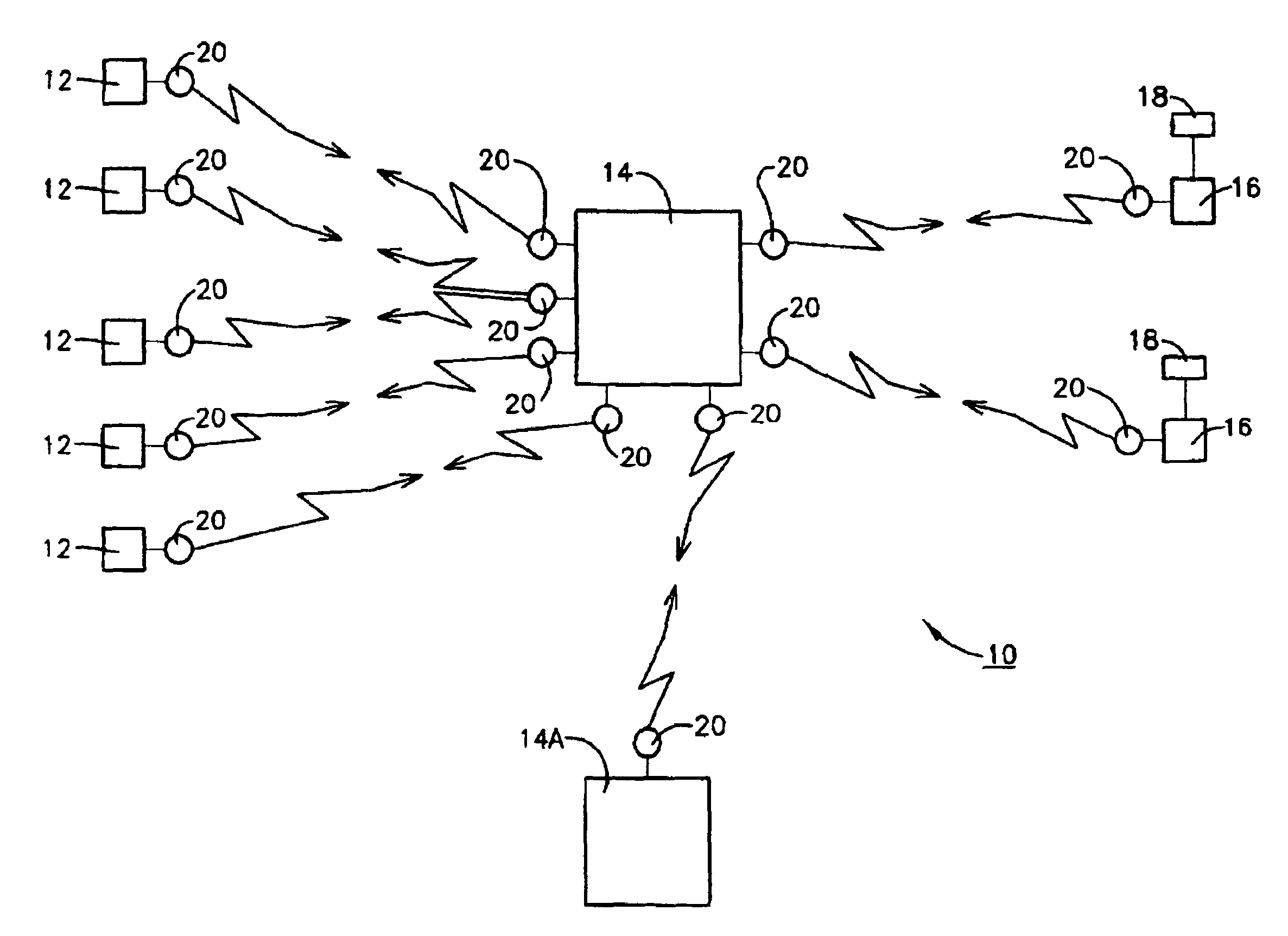
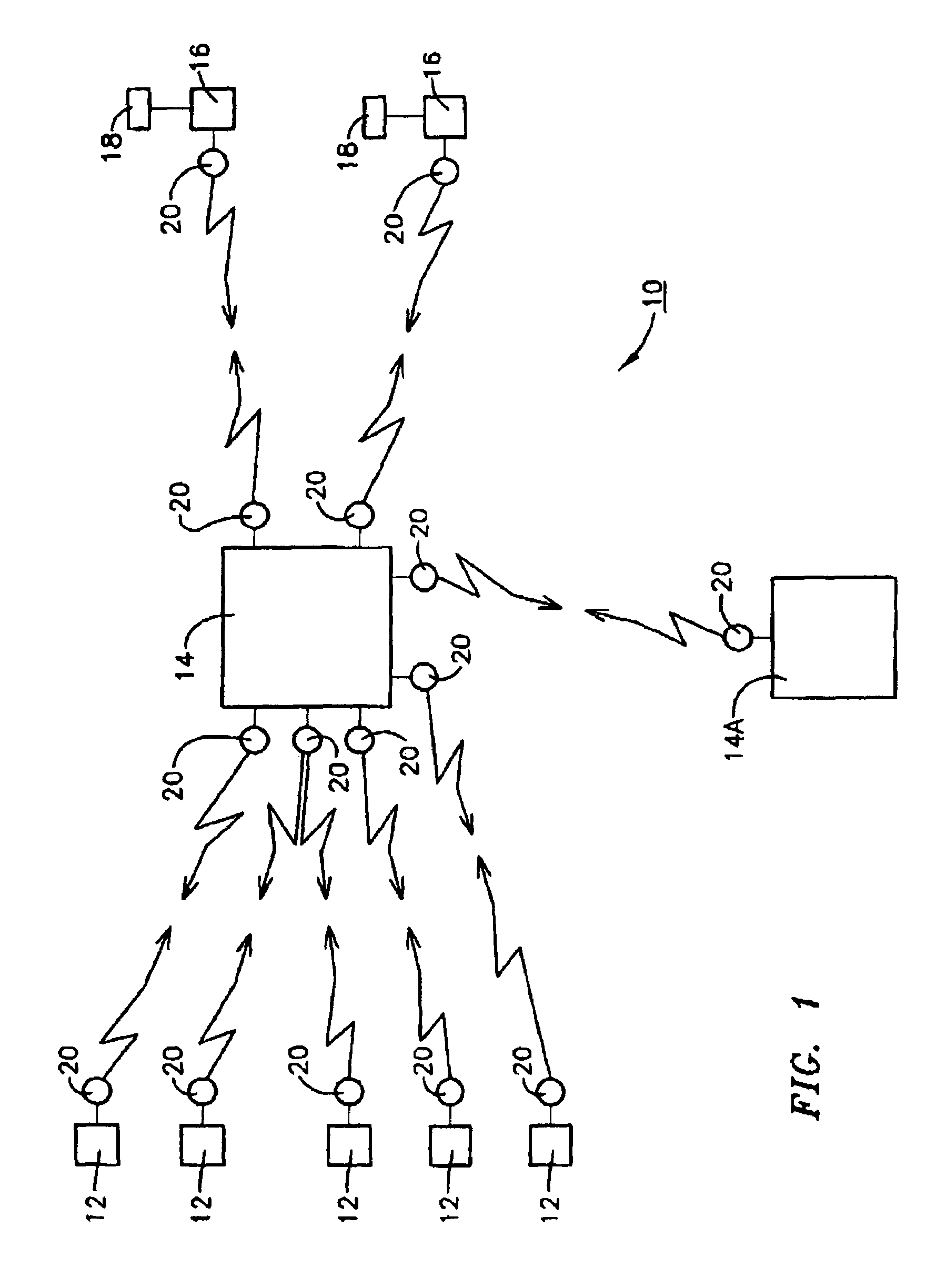
[0013]Referring now to the accompanying drawings, as shown in FIG. 1, the moisture monitoring and control system 10 of the present invention comprises: 1) a plurality of moisture sensors 12; 2) at least one control station 14 capable of monitoring and controlling each of the individual elements of the moisture monitoring and control system; 3) at least one water control valve 16 capable of turning off the water supply to all or at least one water supply zone preferably powered by an aerogel capacitor 18 as described more fully below; and 4) a plurality of non-interfering RF communications devices 20 at each of the sensor, control station and water control valve locations, 12,14 and 16 respectively, providing two way communication between control station(s) 14 and 14A and each of moisture sensors 12 and control valve(s) 16.

[0014]The art is replete with examples of moisture / water sensors 12 that can be used in the successful practice of the present invention, any such prior art device...


PUM

PropertyMeasurementUnit
poweraaaaaaaaaa
areaaaaaaaaaaa
temperatureaaaaaaaaaa

Abstract

A moisture monitoring and control system comprising: 1) a plurality of moisture sensors; 2) one or more local or remote control stations capable of monitoring and controlling each of the individual elements of the moisture monitoring and control system; 3) at least one water control valve capable of turning off the water supply to all or at least one water supply zone and powered by an aerogel capacitor; and 4) a plurality of non-interfering RF communications devices at each of the sensor, control and water control valve locations.

Description

FIELD OF THE INVENTION[0001]The present invention relates to moisture sensing systems and more particularly to such systems for the protection of buildings from flooding.BACKGROUND OF THE INVENTION[0002]The threat of damage from water to a structure whether it be a commercial building, multi-family residence or private home is one that has and continues to be a significant concern to owners and occupiers of such structures. While it is virtually impossible to protect against flooding due to natural occurrences such as hurricanes, torrential rains that cause stream flooding etc., many systems have been developed and marketed for the protection of structures against water damage due to, for example, freezing or breaking pipes, leaking appliances and the like.[0003]Such prior art systems generally comprise: multiple battery powered or hard wired with battery back-up RF communicating moisture or water sensors; hard wired, battery powered or hard wired and battery backed-up water shut of...

Claims


Application Information

Patent Timeline
Patent Type & Authority Patents(United States)
IPC IPC(8): G05D7/00F16K31/12F16K31/36F16K31/48G05D11/00G01N29/00F17D3/00F17D5/02G01F17/00G01F23/00G01H3/00G01L7/00G01N11/00G05B23/02G06F19/00G08B21/00G08B5/22G08C19/00
CPCG01F15/005G01F15/061G08B25/10H04Q9/00G08C23/04G08C17/02G08C2201/51Y10T137/0452Y10T137/7761Y10T137/86397
Inventor KAPLAN, JOSHUA
Owner KAPLAN JOSHUA
Features
  • Generate Ideas
  • Intellectual Property
  • Life Sciences
  • Materials
  • Tech Scout
  • Unparalleled Data Quality
  • Higher Quality Content
  • 60% Fewer Hallucinations
Learn More