Method for replicating snapshot volumes between storage systems
a snapshot image and storage system technology, applied in the field of storage systems, can solve the problem that it is not possible for a local file system of a remote nas system to mount the copied snapshot imag
- Summary
- Abstract
- Description
- Claims
- Application Information
AI Technical Summary
Benefits of technology
Problems solved by technology
Method used
Image
Examples
1st embodiment
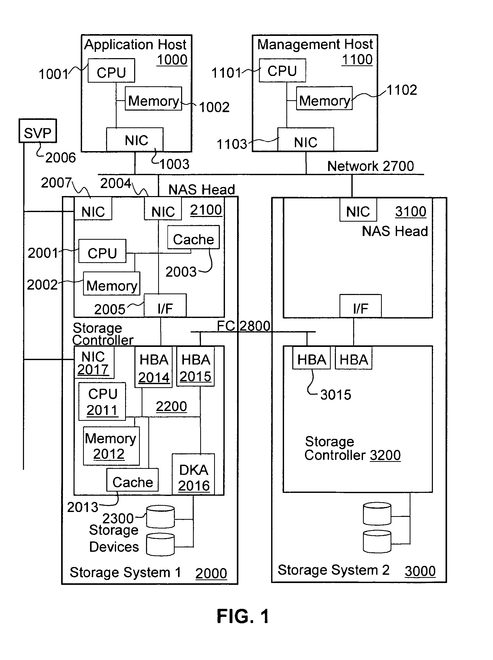
[0033]FIG. 1 shows an example of a hardware configuration in which the method and apparatus of this invention are applied according to a first embodiment. The system includes an Application Host 1000, a Storage Management Host 1100, and Storage Systems 2000 and 3000.
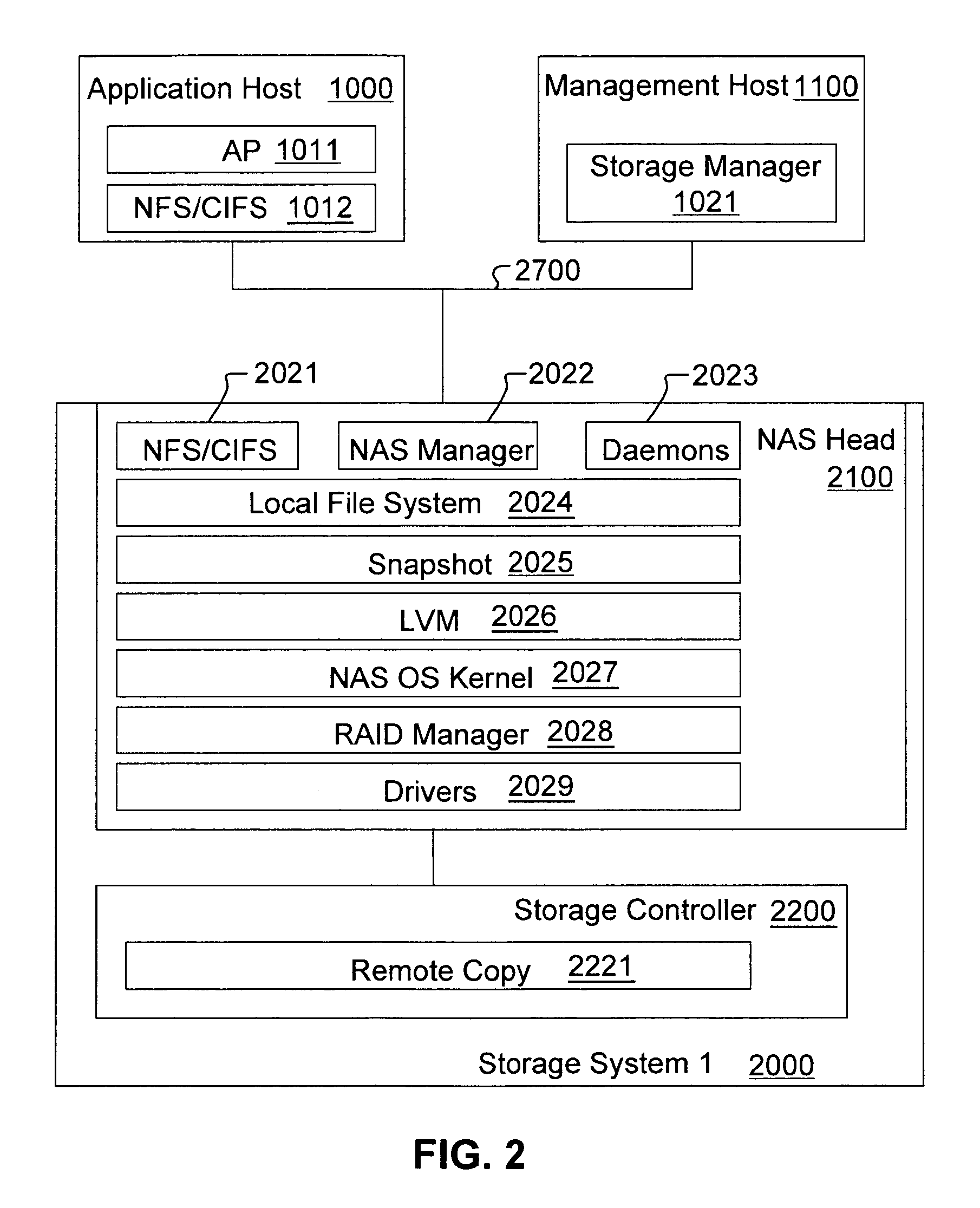
[0034]Application Host 1000 includes a memory 1002 and a CPU 1011 for running an Application System Software (AP) 1011 (illustrated in FIG. 2). The Application System 1011 on the Application Host 1000 issues input / output (I / O) operations to the Storage System 2000, as will be described in more detail below. The Application Host 1000 is connected to the Storage System 2000 via a network interface connection (NIC) 1003. Additional connections to the Storage System 2000 may exist. Moreover, the Application Host 1000 may also be connected to Storage System 3000.
[0035]Storage Management Host 1100 includes a memory 1102 and a CPU 1101 for running a Storage Management Software 1021 (illustrated in FIG. 2). The Storage Managemen...
2nd embodiment
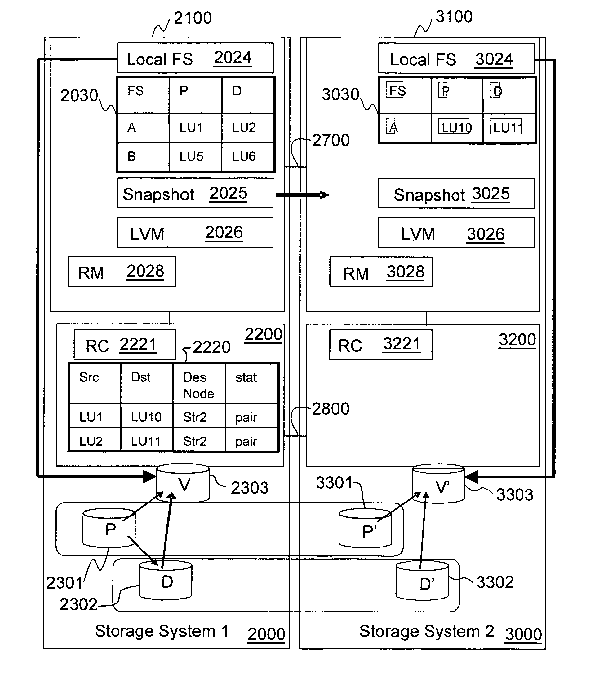
[0057]FIG. 10 shows detailed processes of a second embodiment of the snapshot remote replication system according to the present invention. FIG. 11 is a flow chart illustrating steps performed by snapshot module 2025. Assuming that snapshot operations have already been started, mapping information of P-VOL 2301 and D-VOL 2302 are stored in SVMT 2030. In FIG. 10, a logical unit number of P-VOL 2301 for file system A is LU1. A logical number of D-VOL 2302 for file system A is LU2. First, storage manager 1021 on storage management host 1100 calls a snapshot copy command like “SnapCopy” of snapshot module 2025 with a file system name (A) and target host name (Str2) designating storage system 3000 as the target host (Step 5100). However, in this embodiment, logical unit numbers of both destination P-VOL (P′-VOL) 3301 and destination D-VOL (D′-VOL) 3302 are not designated by the storage management software 1021 (e.g., SnapCopy(FS name, target host)). The snapshot module 2025 checks if the...
3rd embodiment
[0061]The above embodiments extend snapshot operations. In other words, the snapshot module receives a request of snapshot remote replication from the storage management software. According to the third embodiment, the snapshot operation is not extended, but in instead so called “PairCreate” operations to a RAID Manager are extended. This means that the RAID Manager module 2028 receives a request of snapshot remote replication from the storage manager. FIGS. 14 and 15 are directed to this third embodiment of the present invention.
[0062]Assuming that snapshot operations have already been started, the mapping information of P-VOL 2301 and D-VOL 2302 are stored in SVMT 2030. In FIG. 14, a logical unit number of P-VOL 2301 for file system A is LU1. A logical number of D-VOL 2302 for file system A is LU2. Storage Manager 1021 on storage management host 1100 calls a remote replication pair creation command in RAID Manager module 2028 with both source primary volume (P-VOL 2301) and destin...
PUM
 Abstract
Description
Claims
Application Information
 - R&D
- Intellectual Property
- Life Sciences
- Materials
- Tech Scout
- Unparalleled Data Quality
- Higher Quality Content
- 60% Fewer Hallucinations
Browse by: Latest US Patents, China's latest patents, Technical Efficacy Thesaurus, Application Domain, Technology Topic, Popular Technical Reports.
© 2025 PatSnap. All rights reserved.Legal|Privacy policy|Modern Slavery Act Transparency Statement|Sitemap|About US| Contact US: help@patsnap.com


