Seat apparatus for vehicles

a technology for seats and vehicles, applied in the direction of roofs, instruments, process and machine control, etc., can solve the problems of troublesome adjustment, affecting the viewpoint of the driver, and affecting the effect of the driver's viewpoin

Inactive Publication Date: 2008-07-29
HONDA MOTOR CO LTD
View PDF11 Cites 9 Cited by
  • Summary
  • Abstract
  • Description
  • Claims
  • Application Information

AI Technical Summary

Benefits of technology

[0019]With the seat apparatus for vehicles according to the present invention, the seat main body can be traveled to the hip point of a driver by moving the seat main body forward, backward, upward and downward. This makes it possible to give a broader front view to a driver of certain build and to allow the driver to press the pedals without much effort. Consequently, a mechanism for adjusting the pedals forward, backward, upward and downward, which is used in conventional seat apparatuses, are unnecessary. This leads to the cost reduction in vehicle.

Problems solved by technology

As a result, the viewpoint of a driver may deviate from the appropriate one.
In this case, it is hard for the driver to view the front area, especially the area in front of and beneath the vehicle.
However, such an adjustment can be troublesome.

Method used


Image

  • Seat apparatus for vehicles
  • Seat apparatus for vehicles
  • Seat apparatus for vehicles

Examples


first embodiment

(First Embodiment)

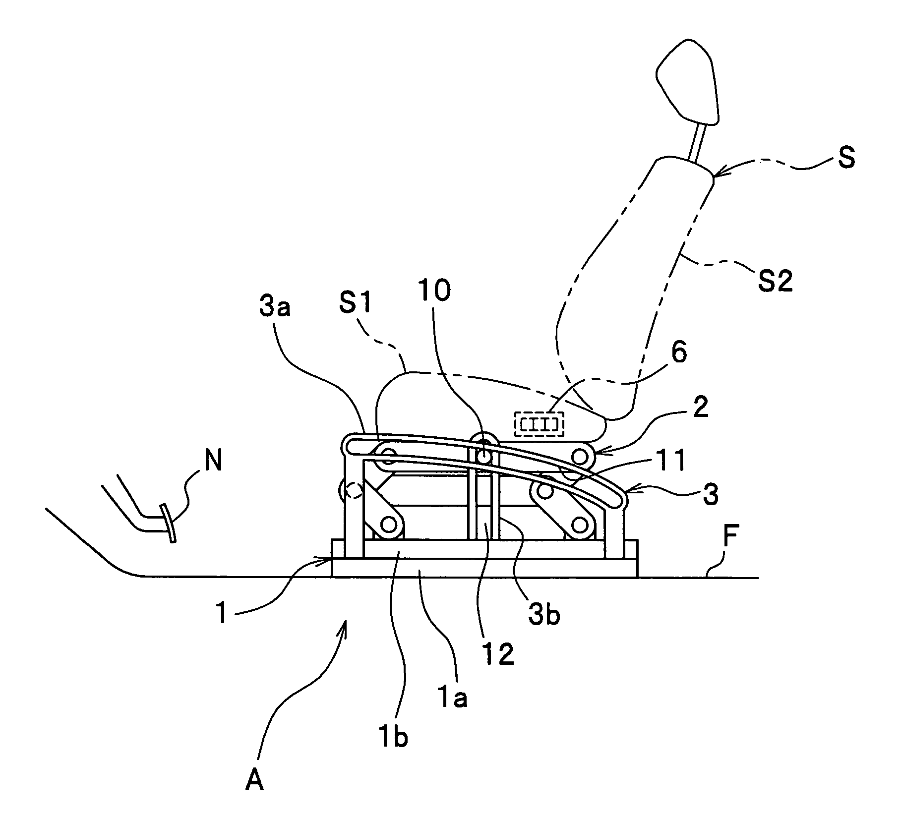
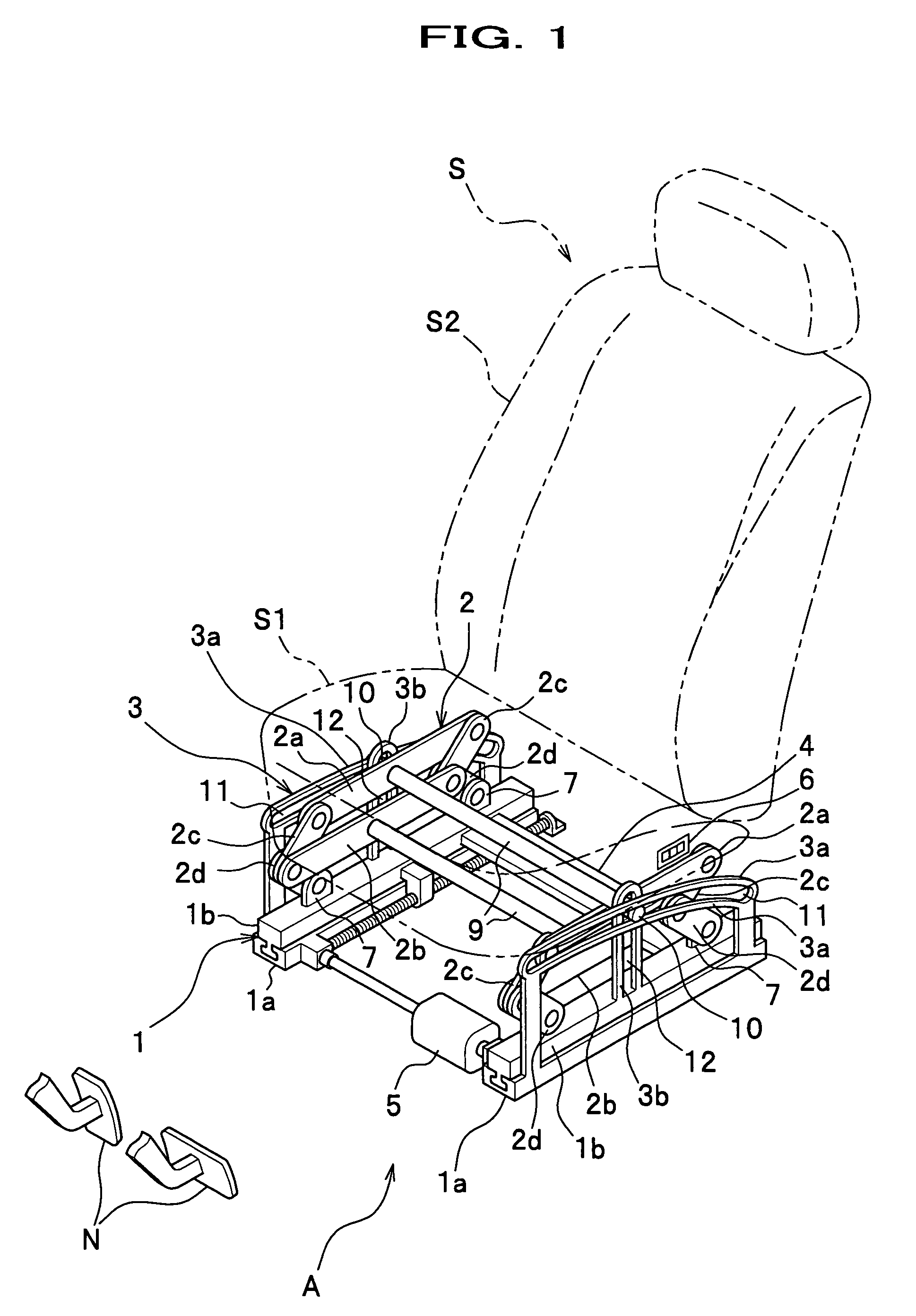
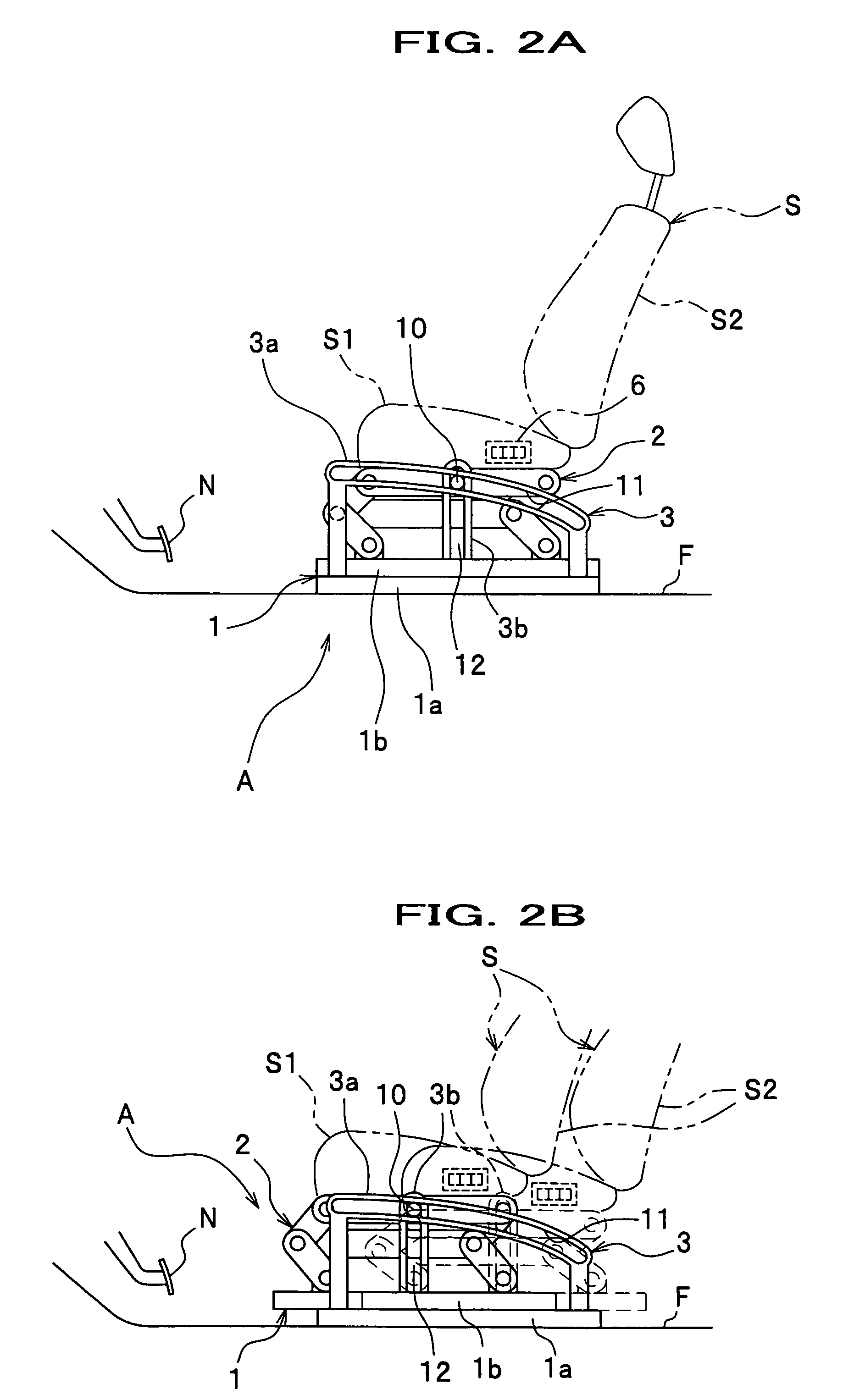
[0036]Referring to FIGS. 1, 2A and 2B, a seat apparatus for vehicles A (refer to a “seat apparatus A” thereafter) supports a seat main body S to move forward, backward, upward and downward. As the seat main body S travels forward, the seat position is made higher. The seat main body S includes a seat cushion S1 and a seat back S2, and it is placed on a floor F through the seat apparatus A. In front of the seat main body S, pedals N including a brake, accelerator and clutch are arranged.

[0037]The seat apparatus A moves the seat main body S to hip points P1, P2 and P3 (see FIGS. 2A, 2B and 9). In other words, the seat apparatus A adjusts the seat main body S such that a driver of a certain build can make an appropriate pose. Specifically, this adjustment is done by moving the seat main body S in an adjusting orbit M (see FIG. 9) as will be described later.

[0038]Note that in the first and second embodiments of the present invention, “forward” is defined as in the dire...

second embodiment

(Second Embodiment)

[0059]Next, a detailed description will be given below, of a seat apparatus for vehicles according to a second embodiment of the present invention. A seat apparatus of a second embodiment is similar to that of the first embodiment, aside from the configuration of the link unit. Therefore, the same reference numerals are given to the same parts as those already described in the first embodiment, and duplicate description is omitted.

[0060]Referring to FIG. 8, a link unit 20 includes a pair of upper links 20a and 20a and a pair of cross links 20b and 20b. The upper links 20a and 20a are provided under the seat cushion S1 of the seat main body S. The cross-shaped cross link 20b fixes the upper link 20a over an area between hinge portions 21 and 22. In this way, the height of the upper link 20a is variable. The link unit 20 allows the seat cushion S1 to stay parallel to the floor F, and its height is variable.

[0061]The link unit 20 has the pin members 10 and 10 on the ...


PUM


Abstract

Disclosed is a seat apparatus for a vehicle, which has the functions of supporting a seat main body being placed on a floor and behind pedals in the vehicle in such a way that the seat main body is movable forward, backward, upward and downward and that the seat main body is made higher in height as it moves forward, and adjusting a position of the seat main body forward, backward, upward and downward in a predetermined adjusting orbit, so that the position fits different builds of drivers. Furthermore, the adjusting orbit is determined based on hip points of the drivers, and the hip points are set on the condition that a viewpoint and heels of the drivers are fixed.

Description

CROSS-REFERENCE TO RELATED APPLICATIONS[0001]This application claims the benefit of Japanese Patent Application 2005-185124 filed on Jun. 24, 2005, the disclosure of which is incorporated herein by reference.BACKGROUND OF THE INVENTION[0002]1. Field of the Invention[0003]The present invention relates to a seat apparatus for vehicles. More specifically, the present invention pertains to a seat apparatus for vehicles which gives a driver a broader view and which allows the driver to push pedals such as a brake without much effort. Further more specifically, the present invention is directed to a seat apparatus for vehicles that permits a driver to adjust a seat forward, backward, upward and downward in accordance with his or her build.[0004]2. Description of the Related Art[0005]In a typical vehicle, a driver's seat is installed on the floor and behind the pedals such as the brake. In addition, the seat is supported by a seat slide unit in such a way to be movable forward and backward...

Claims


Application Information

Patent Timeline
Patent Type & Authority Patents(United States)
IPC IPC(8): B60N2/06
CPCB60N2/0232B60N2/067B60N2/164B60N2/162B60N2/163B60N2/161B60N2/02246
Inventor MARUYAMA, KAZUYUKIMATSUMOTO, YOSHIYUKI
Owner HONDA MOTOR CO LTD
Why Eureka
Try Eureka