Connector, connector assembly and a detection terminal

a technology of detection terminals and connectors, which is applied in the direction of connection, electrical apparatus, coupling device connection, etc., can solve the problems of high cost, inability complicating efforts to meet the demand for miniaturization of connectors, so as to achieve the effect of suppressing quality control costs and reducing production costs

Inactive Publication Date: 2008-07-29
SUMITOMO WIRING SYST LTD
View PDF4 Cites 4 Cited by
  • Summary
  • Abstract
  • Description
  • Claims
  • Application Information

AI Technical Summary

Benefits of technology

[0014]The pivoting portion is at the front part of the lock arm. The accommodating portion for the detection terminal is at the front of the housing and accommodates at least part of the support at the rear of the detection terminal. The action portion is formed at the front of the detection terminal and is displaceable with the pivoting portion of the lock arm so that the contact of the detection terminal can be brought into contact with the mating detection terminal. Thus, a contact position of the contact of the detection terminal and the mating detection terminal is at the front of the housing. Accordingly, the length of the mating detection terminal can be equal to the length of the other signal terminals. As a result, production cost can be reduced by using common terminals as the mating detection terminal and the other signal terminals, and the connector can be miniaturized by shortening the detection terminal.
[0015]The support of the detection terminal is at the rear of the detection terminal. The prior art terminal is supported at the front, and a large support at the front of the prior art terminal would require the contact of the prior art detection terminal to be spaced farther from the front of the housing. As a result, the above-described desirable effects of the detection terminal of the subject invention cannot be obtained. However, the support of the detection terminal of the subject invention is at the rear of the detection terminal, hence a large supporting area is provided between the rear of the detection terminal and the housing. Accordingly, it is not necessary to change the position of the contact from the front of the housing and a dead space in a rear part of the housing can be utilized. Thus, a degree of freedom in setting can be ensured. This eliminates the need to form a press-in portion folded back from the support in addition to the main portion, as in the prior art. Therefore, the structure of the detection terminal can be simplified.
[0016]The action portion and contact portion preferably are arranged to at least partly overlap with respect to forward and backward directions. Thus, the amount that the action portion is displaced by the pivoting portion and the amount that the contact is displaced as the action portion is moved are substantially equal. Accordingly, the action portion is not required to move more than the contact, which in turn reduces the amount that the pivoting portion is required to move. As a result, a pivoting range of the pivoting portion can be narrowed, enabling the miniaturization of the housing.
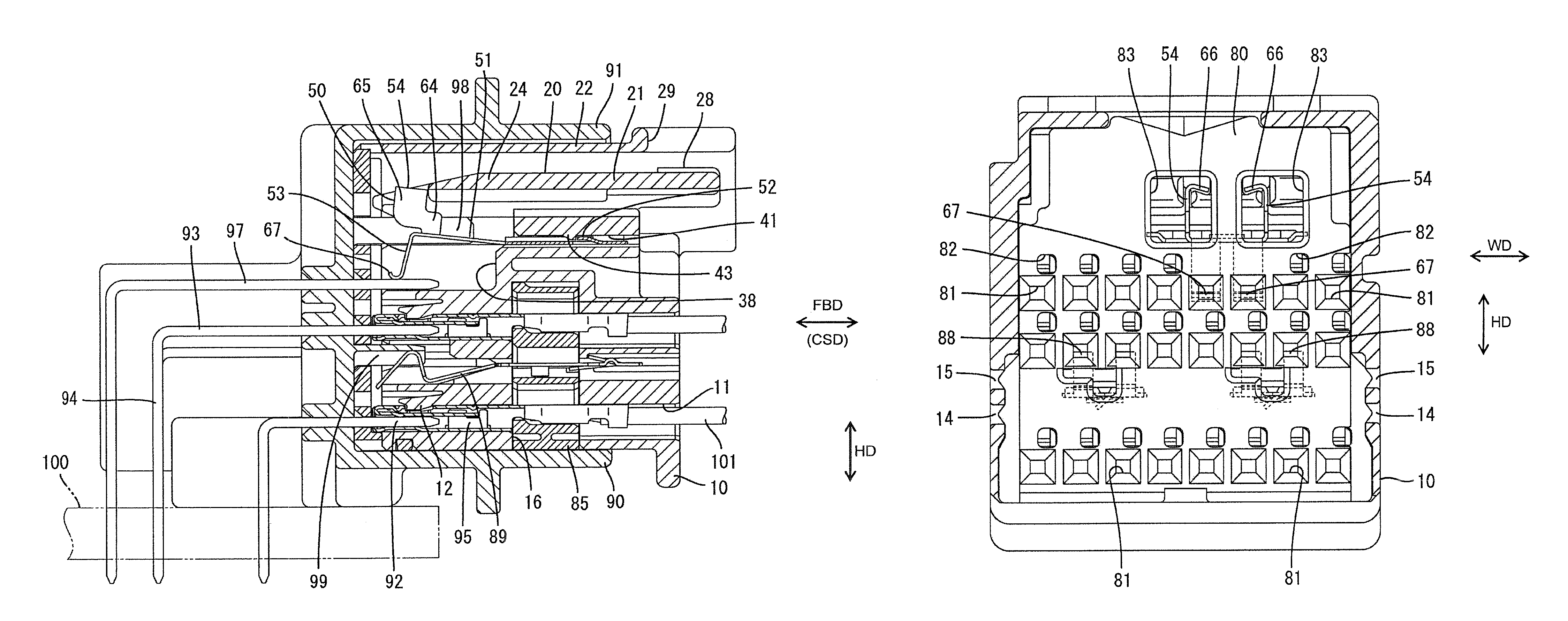
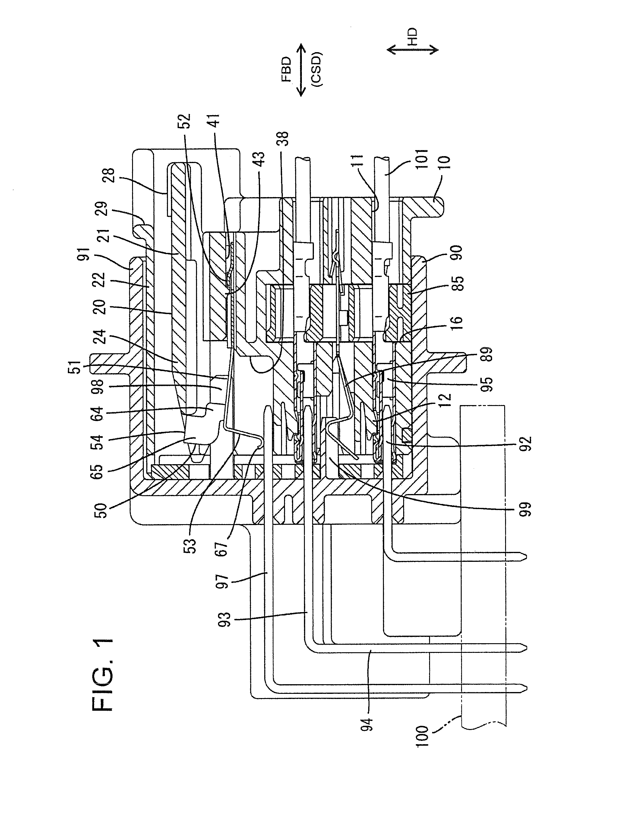
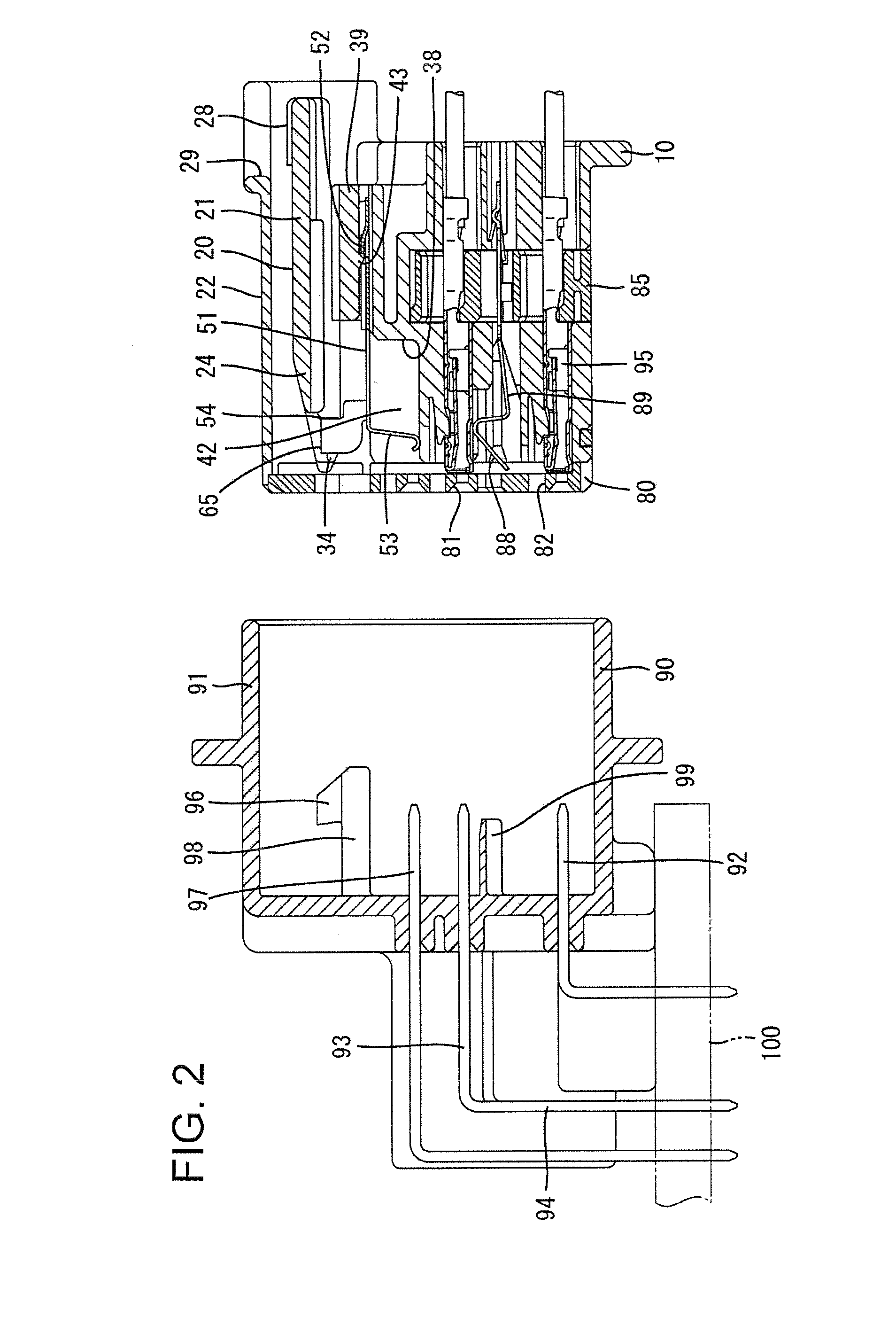
[0021]The contact of the prior art detection terminal contacts the mating detection terminal from below, and it is necessary to ensure an accommodation space for the detection terminal in an area below the mating detection terminal in the mating housing. In contrast, the pivoting portion of the detection terminal of the subject invention is lifted up when the housings are connected partly. The action portion of the detection terminal of the subject invention engages the pivoting portion and the contact hangs down from the main portion. Thus, unlike the prior art, the contact engages the mating detection terminal from above, and the mating detection terminal can be at a lower height position. Further, the bottom end of the contact is at substantially the same height as the adjacent signal terminals in the housing, and hence the mating detection terminal also is at substantially the same height as the adjacent signal terminals. Thus, unlike the prior art, the mating detection terminal is not arranged above the other signal terminals. Accordingly, the mating detection terminal of the invention is protected by the surrounding signal terminals, and the rib or protection wall of the prior art is not necessary. Thus, production cost can be reduced further.
[0022]The contact of the prior art connector is retracted from the front of the housing. However, at least part of the contact of the subject invention preferably is exposed at the front of the housing. Thus, the height of the contact can be checked easily from the front of the housing and quality control costs can be suppressed.

Problems solved by technology

As a result, the above-described connector cannot meet demands for miniaturization and costs are high.
Accordingly, the pivoting portion of the lock arm must be able to deform a large amount, thereby further complicating efforts to meet demands for miniaturization of the connector.
This results in the extension of the mating detection terminal, and hence a very large supporting area can not be ensured.
Therefore, the press-in portion and main body must be formed separately at opposite sides of the support by folding, which has caused a problem of complicating the structure of the detection terminal.

Method used


Image

  • Connector, connector assembly and a detection terminal
  • Connector, connector assembly and a detection terminal
  • Connector, connector assembly and a detection terminal

Examples


Embodiment Construction

[0036]A connector according to a preferred embodiment of the invention is an airbag connector and has a housing identified by the numeral 10 in FIGS. 1-4, 6 and 7. The housing 10 is connectable with a mating housing 90. It should be noted that an end of the housing 10 that is to be connected with the mating housing 90 is referred to herein as the front end concerning forward and backward directions FBD.

[0037]The mating housing 90 is made e.g. of a synthetic resin and includes a fitting tube 91 of substantially rectangular cross-section. Male terminal fittings 92 are mounted through the back wall of the fitting tube 91, as shown in FIG. 2. Each male terminal fitting 92 is bent into an L-shape, and includes horizontal and vertical sections 93 and 94 respectively. The horizontal sections 93 extend in substantially forward and backward directions FBD and leading ends of the horizontal sections 93 project into the fitting tube 91. The vertical sections 94 extend substantially perpendicul...


PUM


Abstract

A housing (10) has a lock arm (20) that pivots about a fulcrum (23) that is rearward of a pivoting portion (24) of the lock arm (20). A detection terminal (50) has a rear support (52) supported on the housing (10) rearward of the pivoting portion (24). An action portion (54) of the detection terminal (50) is engaged with the pivoting portion (24) and displaces with the pivoting portion (24). The lock arm (20) deforms during connection of the housing (10) and a mating housing (90) so that contacts (53) of the detection terminal (50) are not in contact with mating detection terminals (97). However, the lock arm (20) returns resiliently when the housings (10, 90) are connected properly so that the contacts (53) contact the mating detection terminals (97).

Description

BACKGROUND OF THE INVENTION[0001]1. Field of the Invention[0002]The invention relates to a detection terminal, a connector and a connector assembly with a detection terminal.[0003]2. Description of the Related Art[0004]U.S. Pat. No. 6,045,395 discloses a connector with a housing and a mating housing that are connectable with one another. A detection terminal is inserted into the housing from behind and contacts a mating detection terminal in the mating housing when the housings are connected properly. A resiliently deformable lock arm is cantilevered backward from the front end of the housing, and has an end that is movable vertically relative to the front end.[0005]The detection terminal is below the lock arm, and includes a support that is supported on a front inner wall of the housing. A main body extends obliquely up towards the back from the support. A rear part of the main body is angled to project up to define an action portion that can be pressed by the pivoting portion of t...

Claims


Application Information

Patent Timeline
Patent Type & Authority Patents(United States)
IPC IPC(8): H01R13/627
CPCH01R13/641H01R13/6272
Inventor KOBAYASHI, YUTAKANAKAMURA, KEIICHINORO, YUTAKAKIKUCHI, TAKAHIROISHIKAWA, YOSHIYUKI
Owner SUMITOMO WIRING SYST LTD
Why Eureka
Try Eureka