Gas sensor

a technology of gas sensor and sensor, which is applied in the field of gas sensor, can solve the problems of manpower and consequent costs, and achieve the effects of reducing calibration error due to increased pressure of calibrating gases in the area of the measuring cell, and reducing maintenance and calibration effor

Active Publication Date: 2008-08-05
DRAGER SAFETY
View PDF36 Cites 43 Cited by
  • Summary
  • Abstract
  • Description
  • Claims
  • Application Information

AI Technical Summary

Benefits of technology

[0012]Due to the use of a cap made of a porous, gas-permeable and water-impermeable material for delimiting the gas sensor from the environment according to the principal claim, it is achieved that the diffusion of gas from the environment into the measuring cell is hindered to a very limited extent only, so that the cap can also remain mounted on the gas sensor during the measuring operation, as a consequence of which the maintenance effort is substantially reduced.
[0014]According to another preferred embodiment, the cap and the calibrating adapter are permanently connected to the gas sensor both during the use for measurement and during the calibration, so that the maintenance and calibration effort is considerably reduced with a permanently installed calibrating gas feed line especially in case of gas sensors installed at poorly accessible sites.
[0015]The invention provides an improved gas sensor, which is better protected against harsh environmental conditions and at the same time creates the precondition, due to the safety device used, of continuing to be provided with a special calibrating adapter during the calibration with a calibrating gas as well, so that the measuring and maintenance effort required for the measurement and the calibration at the gas sensor is substantially reduced.

Problems solved by technology

One drawback of the prior-art calibrating adapter is that free diffusion of the gas to the measuring cell is prevented by the calibrating adapter itself, so that the calibrating adapter is placed on the gas sensor for the duration of the calibration only and must subsequently be removed in an additional operation.
This is associated with manual effort and consequently costs especially in case of stationarily installed gas sensors at poorly accessible measuring sites or under difficult environmental conditions involving exposure to wind or health hazard.

Method used


Image

  • Gas sensor
  • Gas sensor
  • Gas sensor

Examples


Embodiment Construction

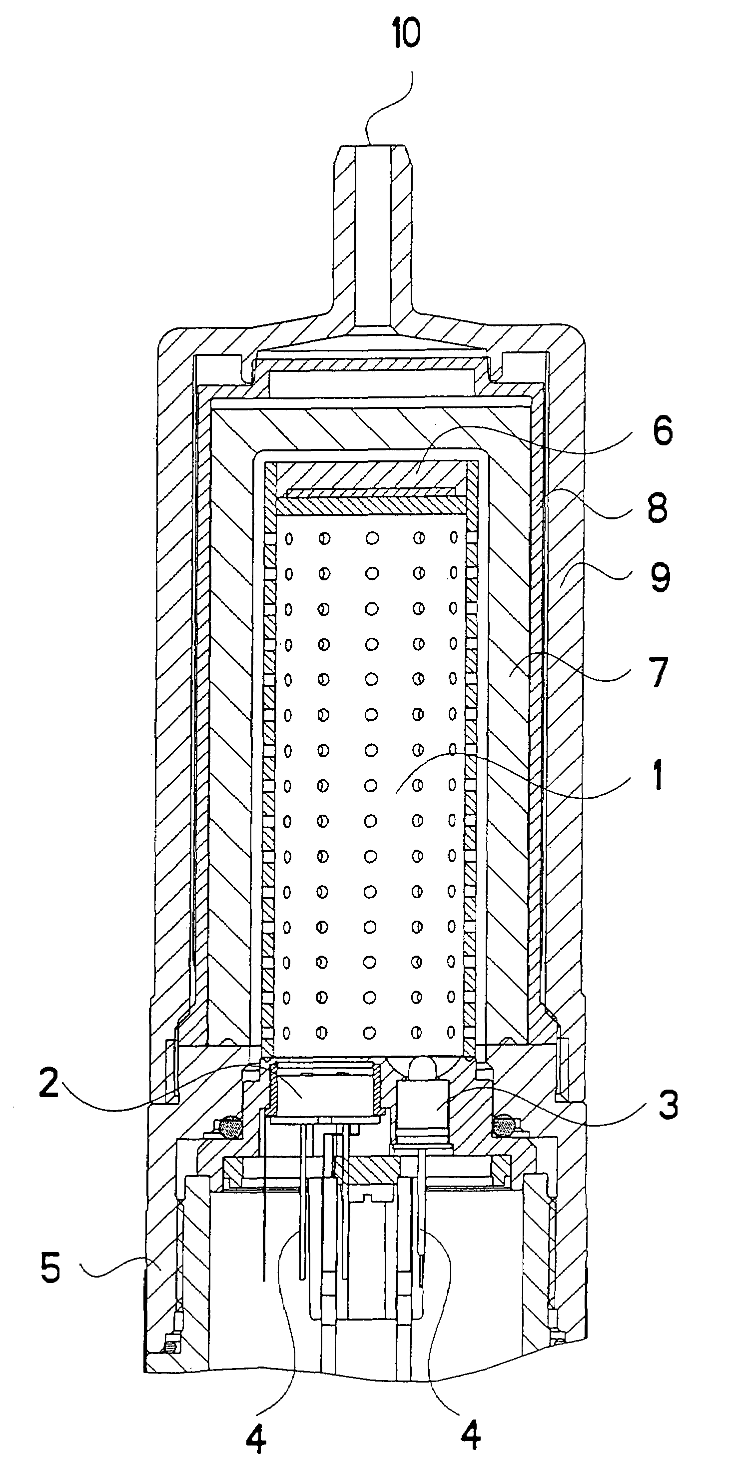
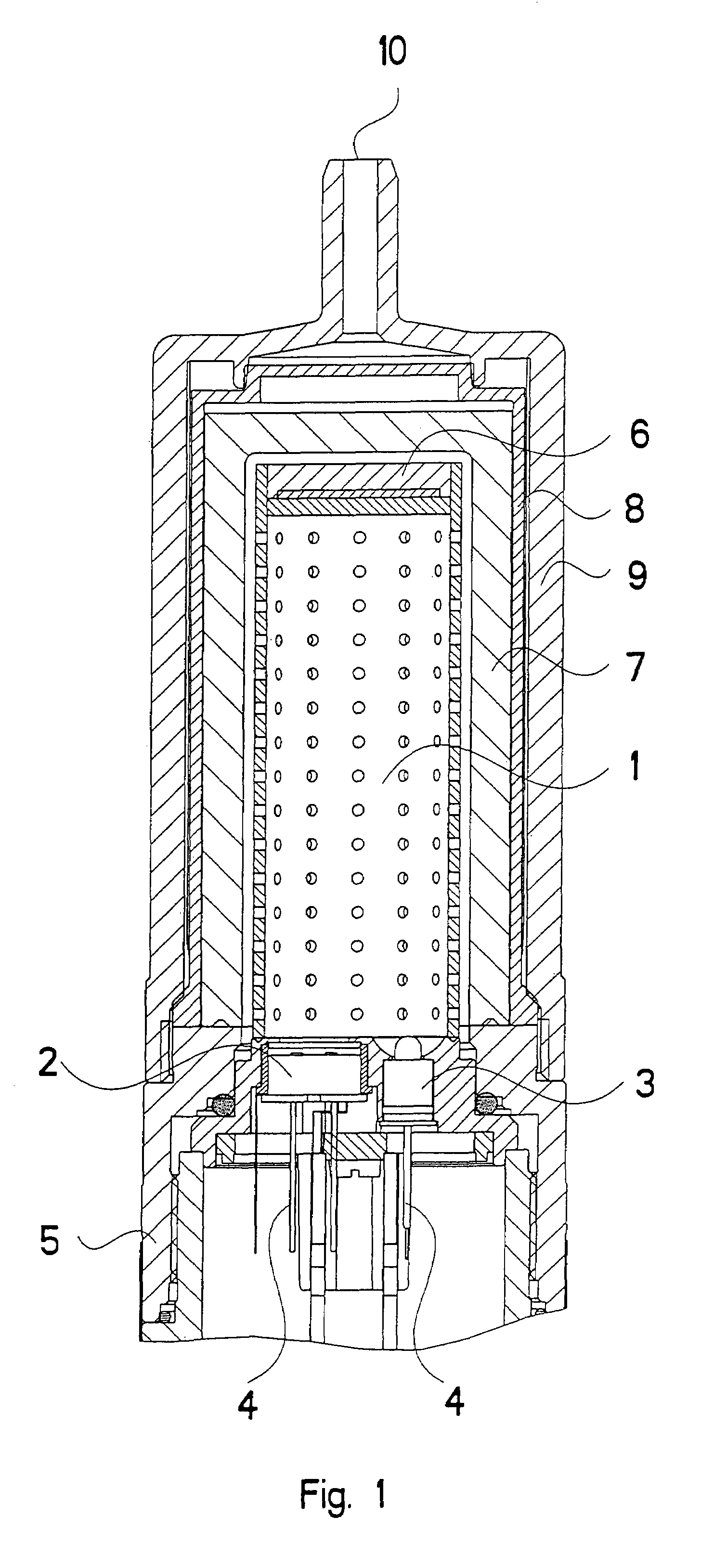
[0021]Referring to the drawings in particular, the gas sensor in FIG. 1 is an infrared optical gas sensor with a radiation source 3 and with a measuring element 2 designed as an infrared detector, both of which are arranged in the base area 5 of the gas sensor, which said base area is made of metal or even a plastic. The electric contacts 4 are connected to an electronic evaluating unit of the gas sensor, which joins the base area 5. The cylindrical measuring gas cuvette 1 has a radiation-reflecting design on the inside in case of the infrared optical gas sensor and has perforations, which are distributed over the jacket surface and make possible the diffusion of the gas, whose concentration is to be measured, into the cuvette. Such a gas sensor is, for example, a stationary gas sensor installed at a certain measuring site, which may be poorly accessible, as it is used, for example, in industrial or process plants in the chemical or petroleum / natural gas industry. Especially in case...


PUM

PropertyMeasurementUnit
dynamic pressureaaaaaaaaaa
thicknessaaaaaaaaaa
dynamic pressureaaaaaaaaaa

Abstract

A gas sensor is provided that is delimited from the environment with a preferably replaceable cap (8) made of a porous, gas-permeable and water-impermeable material, especially sintered PTFE. The gas sensor is protected against environmental moisture and can be permanently provided with the cap (8) and with a special calibrating adapter (9) both during the gas measurement and during the necessary calibration. Due to the special design of the cap (8) and the calibrating adapter (9), the gas sensor offers the possibility of remote calibration, which can be carried out with high accuracy and is independent from weather effects, especially wind.

Description

CROSS REFERENCE TO RELATED APPLICATIONS[0001]This application claims the benefit of priority under 35 U.S.C. § 119 of German Patent Application 10 2005 003 050.5 filed Jan. 22, 2005, the entire contents of which are incorporated herein by reference.FIELD OF THE INVENTION[0002]The present invention pertains to a gas sensor with a measuring element, which generates a measured signal that depends on the concentration of the measured gas.BACKGROUND OF THE INVENTION[0003]Examples of such gas sensors are infrared optical and electrochemical gas sensors as well as catalytic heat tone sensors. Within their housings, these gas sensors have a measuring cell, in which the gases to be measured are detected on the basis of physical or chemical processes. Depending on the conditions of use, regular calibration with a calibrating gas of known concentration is to be performed for the operation of such gas sensors. According to the current state of the art, this is carried out, as a rule, by pulling...

Claims


Application Information

Patent Timeline
Patent Type & Authority Patents(United States)
IPC IPC(8): G01N21/00G01N33/22
CPCG01N21/09G01N33/0006G01N21/3504G01N27/16G01N21/61G01N33/006
Inventor LANGE, BJORNHAACK, NILSWULF, LARSCHRZAN, RIGOBERT
Owner DRAGER SAFETY
Why Eureka
Try Eureka