
Communication device holder for vehicles

a technology for communication devices and vehicles, applied in the direction of machine supports, transportation and packaging, other domestic objects, etc., can solve the problems of affecting driving safety, unable to be received or held tightly, and displaced to some corners, so as to facilitate use flexibility

Inactive Publication Date: 2008-08-05
SUPA TECH
View PDF10 Cites 77 Cited by
  • Summary
  • Abstract
  • Description
  • Claims
  • Application Information

AI Technical Summary

Benefits of technology

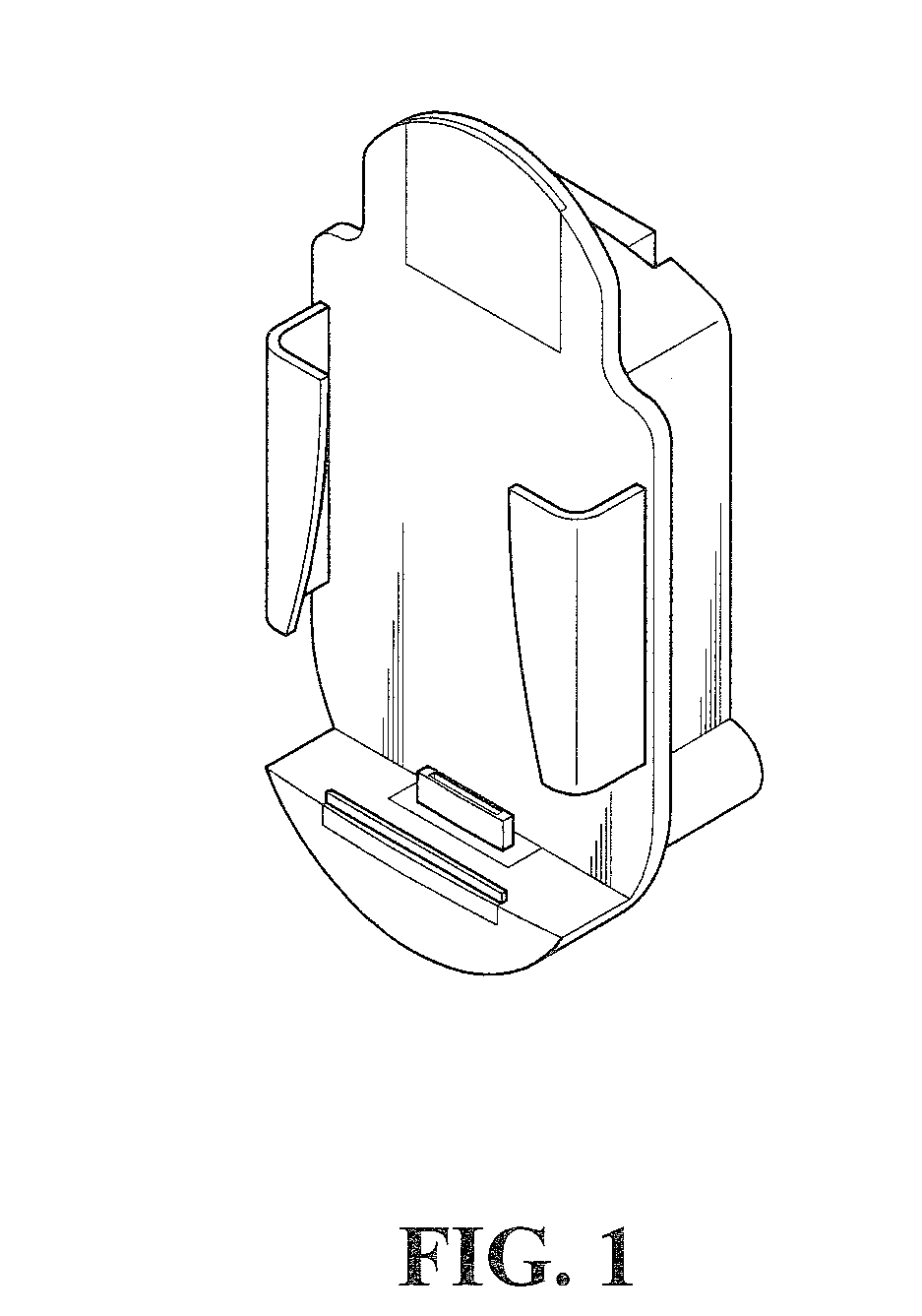
[0006]An objective of the present invention is to provide a communication device holder for vehicles, which has a simpler structure and is easier to use, and can effectively clamp a communication device inside the communication device holder for vehicles.
[0016]The space in between the clamping pawls of the present invention is adjustable for facilitating usage flexibility. In addition, when the communication device is received in the clamping holder, by adjusting the space in between the clamping pawls, the communication device can be fixedly clamped tightly and effectively.

Problems solved by technology

When these electronic products are used in the home or in the office, they can be placed in a convenient and safe place for future use; however, it will be very dangerous when these electronic products are placed haphazardly in a car after use, especially due to changes in road conditions and car movements, these electronic terminals could be displaced to some corners to affect the driving safety.
Nevertheless, these kinds of clamping holders are only usable for holding communication devices which have compatible sizes to the clamping holders, which means that, if the communication devices have larger or smaller sizes than the clamping holder, they are either unable to be received or unable to be held tightly, thereby failing to hold the communication devices effectively.

Method used


Image

  • Communication device holder for vehicles
  • Communication device holder for vehicles
  • Communication device holder for vehicles

Examples


Embodiment Construction

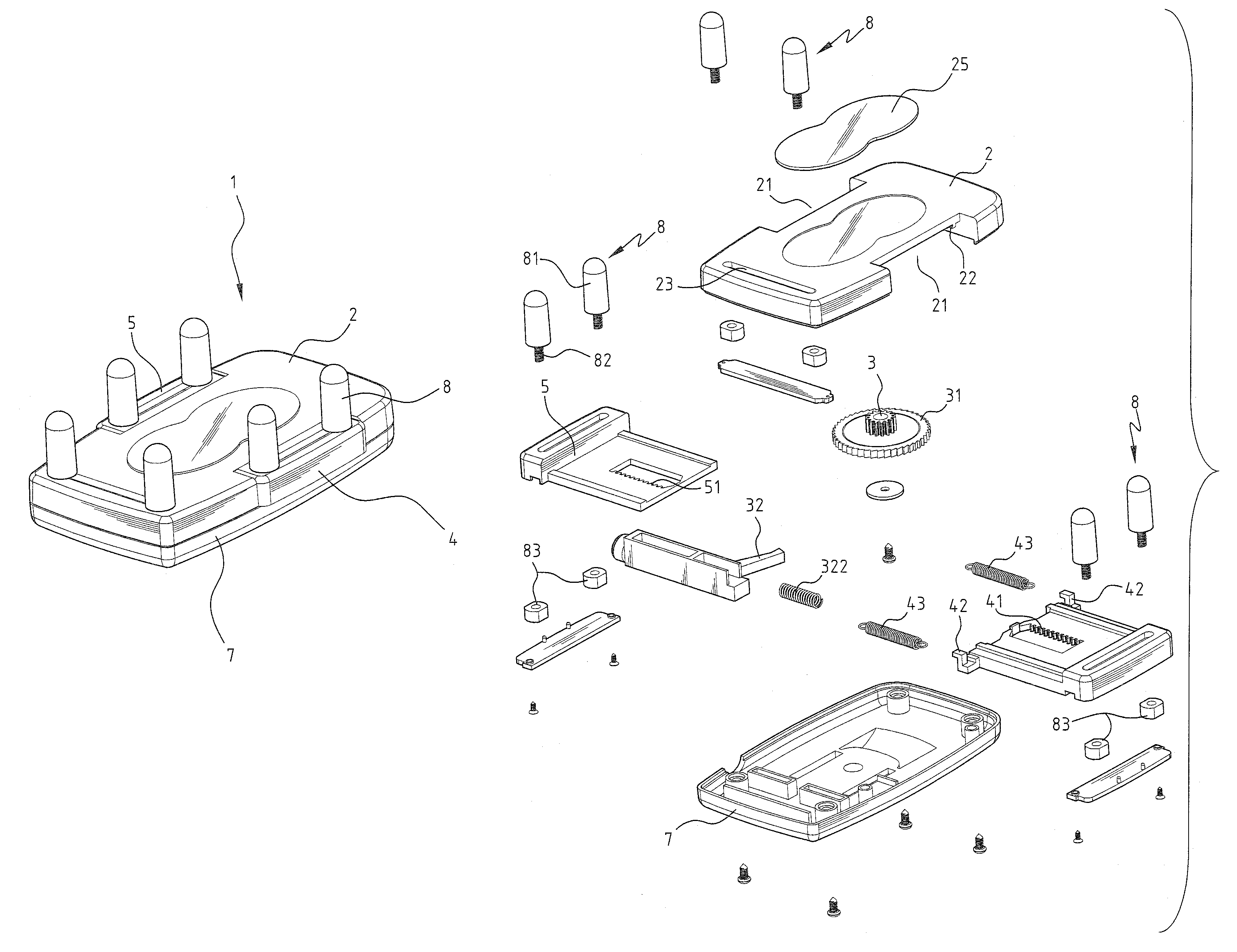
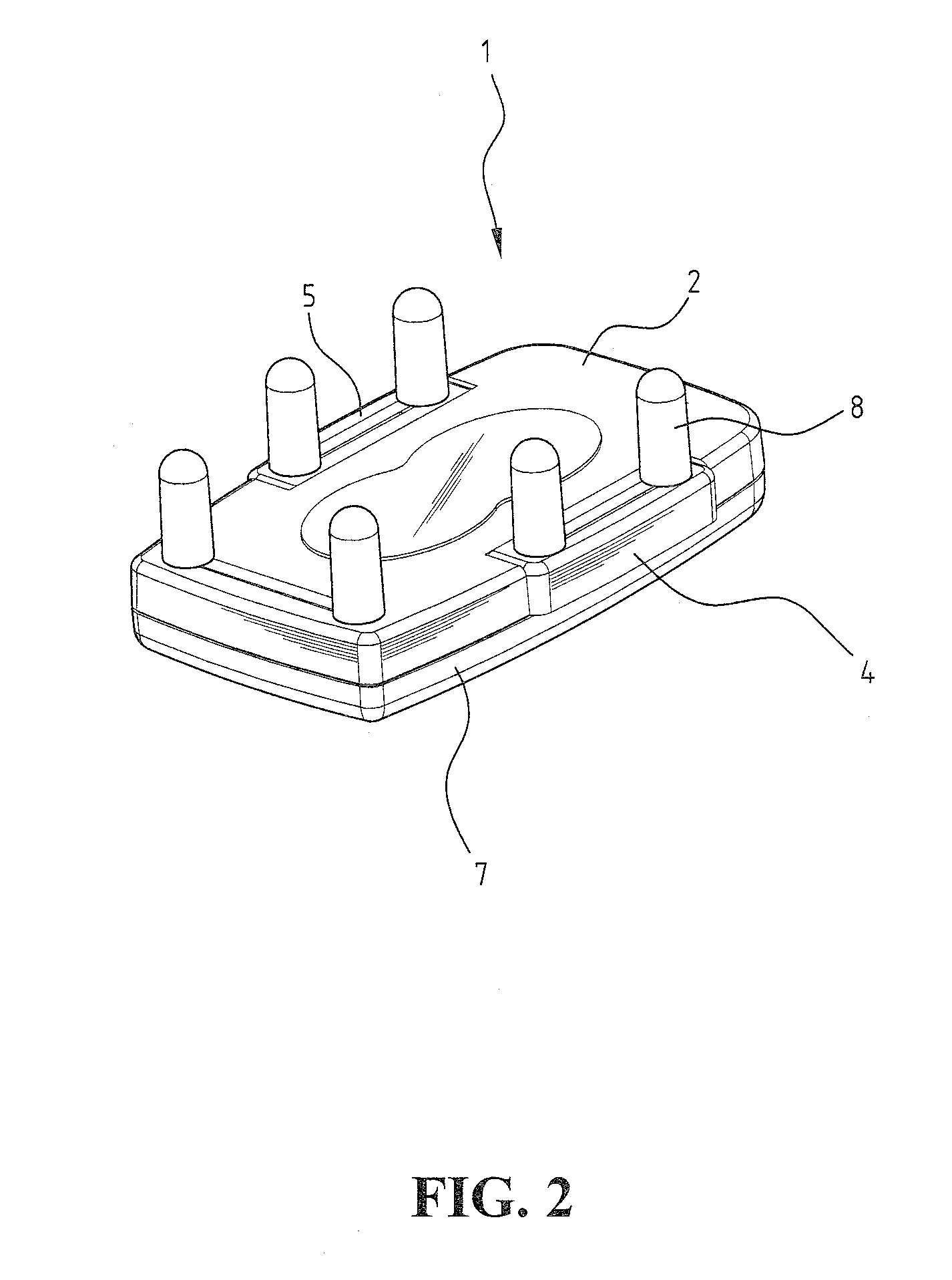
[0024]Referring to FIGS. 3-5, a preferred embodiment of the communication device holder for vehicles 1 according to the present invention comprises an upper cover 2 and a lower cover 7 cooperating with the upper cover 2. The upper cover 2 and the lower cover 7 are sealed to form an internal space.

[0025]The two sides of the upper cover 2 are formed with a plurality of openings 21, respectively. A left wing member 5 and a right wing member 4 are inserted into the inside of the upper cover 2 via the openings 21. To ensure the stability of the horizontal movement of the left wing member 5 and the right wing member 4 in between the upper cover 2 and the lower cover 7, a plurality of guide rails 22 are provided at the contact region between the upper cover 2 and the left wing member 5 and the right wing member 4, thereby making the left wing member 5 and the right wing member 4 to move horizontally inside the frame formed by the guide rails 22 to improve the stability.

[0026]Each end of th...


PUM


Abstract

A communication device holder for vehicles includes an upper cover and a lower cover cooperating with the upper cover; a left wing member and a right wing member, which are horizontally displaceable, are disposed in between the upper cover and the lower cover; one end of the left wing member is formed with at least one clamping jaw, and the other end of the left wing member is formed with a horizontal rack; one end of the right wing member is formed with at least one clamping jaw, and the other end of the right wing member is formed with the horizontal rack and at least one raised portion, and the raised portion is connected with a post formed on the upper cover through a spring; the spring pushes the right wing member to displace towards the outside of the upper cover.

Description

BACKGROUND OF THE INVENTION[0001]1. Field of the Invention[0002]The present invention is generally related to a communication device holder, and in particular, to a communication device holder for vehicles.[0003]2. The Prior Arts[0004]Nowadays, people are using digital electronic products like cell phones and PDAs in many more occasions, such as in an office, a home or in a car. When these electronic products are used in the home or in the office, they can be placed in a convenient and safe place for future use; however, it will be very dangerous when these electronic products are placed haphazardly in a car after use, especially due to changes in road conditions and car movements, these electronic terminals could be displaced to some corners to affect the driving safety.[0005]To solve the aforementioned problem, some clamping holders for holding the electronic products have appeared on the market, whose principle of clamping or holding is to adopt a holder of a specific designated ...

Claims


Application Information

Patent Timeline
IPC IPC(8): A47F5/00
CPCB60R11/0241B60R11/0258B60R11/0252B60R2011/0059
Inventor CHEN, JEONG-SHIUN
Owner SUPA TECH
Learn More