Microlithographic exposure method as well as a projection exposure system for carrying out the method

a technology of exposure system and exposure method, which is applied in the direction of microlithography exposure apparatus, printers, instruments, etc., can solve the problems of polarization-changing effects of light passing through, stress birefringence is frequently observed to a disturbing extent, and the width of imaged structures is varied over their direction, so as to achieve the effect of reducing the number of times and cost advantages for adjustment and maintenan

Inactive Publication Date: 2008-08-05
CARL ZEISS SMT GMBH
View PDF52 Cites 88 Cited by
  • Summary
  • Abstract
  • Description
  • Claims
  • Application Information

AI Technical Summary

Benefits of technology

[0022]The invention makes it possible to effectively correct polarization aberrations, that is to say effects which are related to the vector character of the electric field. One major advantage of the invention is that variable adjustment of the output polarization state also makes it possible to control and minimize those imaging errors which can occur only during operation of a projection exposure system, for example in situ at the premises of the manufacturer of semiconductor components or other microstructured devices. This is because it is necessary to take account of the fact that the residual absorption of the optical elements of a lithography objective can lead to heating, which can itself lead to mechanical stresses which in turn can lead to the creation or variation of the birefringent effect in correspondingly susceptible materials. In this case, the spatial patterns of the heating are generally application-specific and can therefore not be taken into account for all time by an optimized design of a projection exposure system. Further changes in the polarization effect during the life of a projection exposure system can be caused by radiation-induced and contamination-induced layer degradation, relaxation of stresses or else by position changes of elements that produce a polarization effect, for example by shifting and tilting. Since it is possible in the case of projection exposure systems according to the invention to set the output polarization state variably by means of suitable polarization manipulation, it is possible to react at short notice to such polarization changes, in order to keep the imaging performance within predetermined specifications overall.
[0023]In particular, it is thus possible for the illumination system and / or the projection objective to contain at least one optical element which causes disturbance of the polarization distribution over the cross section of a beam, and for the output polarization state to be adjusted so as to at least partially compensate for this disturbance or interference. One or more polarization manipulation devices which are used for this purpose can accordingly be configured, or can be adaptively configured, as a compensator or compensators for partial or complete compensation of such disturbances.
[0024]The adjustment of the output polarization state according to the invention is accordingly carried out in preferred variants during the operation of the projection illumination system, in particular at its point of use.
[0025]An adjustment process can be carried out away from the point of use, for example at the manufacturer's premises, for example for adjustment work before initial use and / or during maintenance work. Considerable time and cost advantages for adjustment and maintenance can be achieved with the aid of the invention.
[0026]For the purposes of this application, a “polarization manipulation device” is a device with one or more components which have a polarization-optical effect, can change the polarization state of the incident radiation in a manner which can be predetermined in a defined manner, and which is alternatively also referred to in the following text as “polarization elements”. These may be integral or formed from two or more parts. In this case, a polarization manipulation device is alternatively also referred to as a polarization manipulator and has at least two different configurations, which correspond to different polarization-optical effect functions.
[0027]The possible polarization state changes include in particular deliberate position-dependent modification of the polarization state over the cross section of a radiation beam. Polarization elements with an effect which depends on the position are also referred to in the following text as being “position-variant” or “space-variant”.

Problems solved by technology

Owing to stress-induced and / or intrinsic birefringence, they can cause polarization-changing effects on the light passing through them.
Stress birefringence is likewise frequently observed to a disturbing extent.
Unfavorable polarization states can lead to a variation in the width of imaged structures over their direction.
Furthermore, undesirable nonlinear relationships may occur between the size of the structure to be imaged and the size of the imaged structure.
In addition, unfavorable polarization states can induce telecentricity errors, which can lead to undesirable distortion between different adjustment planes.
In consequence, light which is still unpolarized in the reticle plane is partially polarized in the image plane, which is said to lead to direction dependency of the imaging characteristics.

Method used


Image

  • Microlithographic exposure method as well as a projection exposure system for carrying out the method
  • Microlithographic exposure method as well as a projection exposure system for carrying out the method
  • Microlithographic exposure method as well as a projection exposure system for carrying out the method

Examples


Embodiment Construction

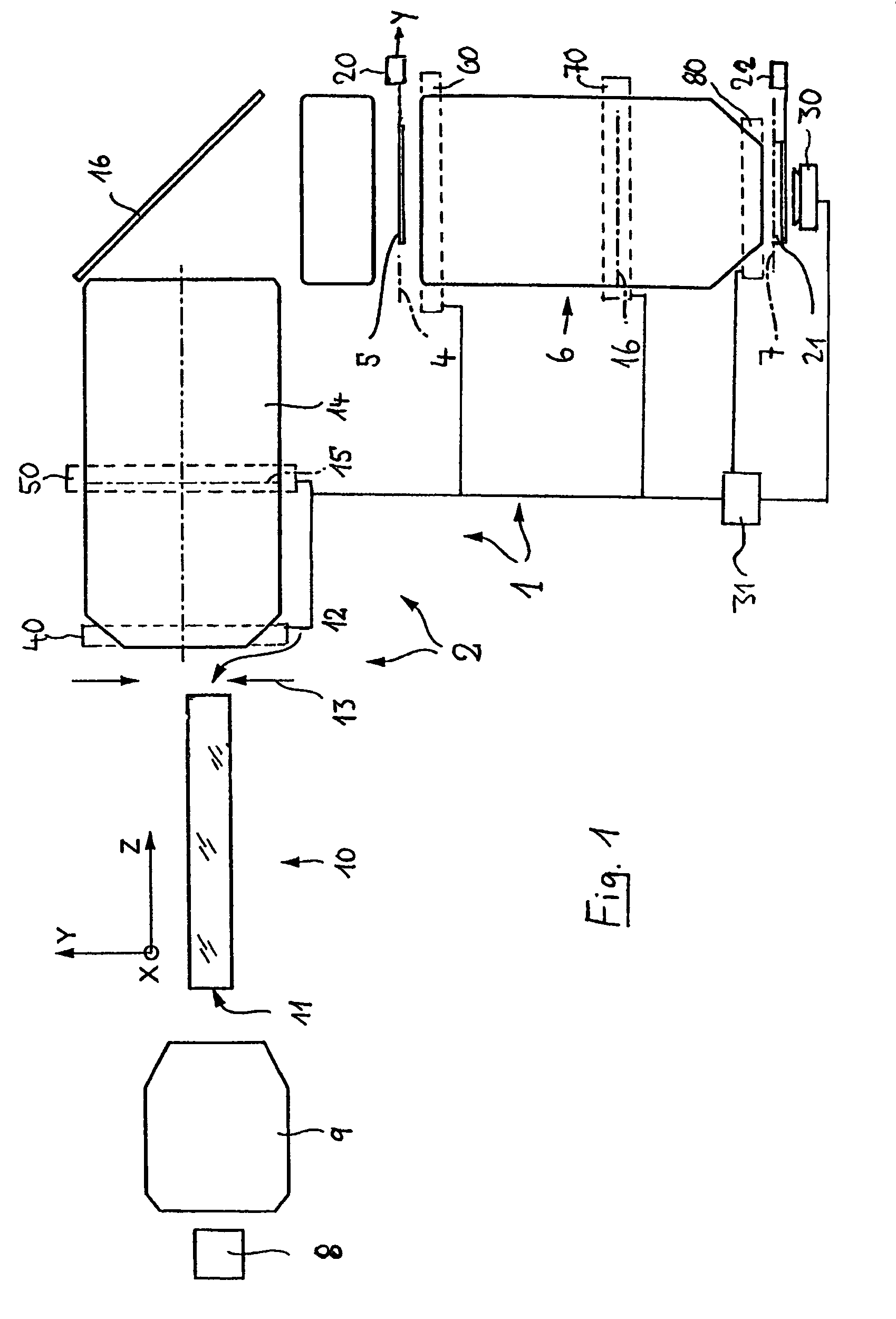
[0056]FIG. 1 shows an example of a projection exposure system 1 for microlithographic production of integrated circuits and other finely structured components with resolutions down to fractions of 1 μm. The installation 1 comprises an illumination system 2 for illumination of a photomask 5 which is arranged in the outlet or image plane 4 of the illumination system, as well as a projection objective 6 which images the pattern of the photomask that is arranged in its object plane 4 onto the image plane 7 of the projection objective on a smaller scale. A semiconductor wafer which is coated with a light-sensitive layer is located, for example, on the image plane 7.

[0057]A laser 8 is used as the light source for the illumination system 2, for example an excimer laser used in the deep ultraviolet band (DUV) and with an operating wavelength of 248 nm, 193 nm or 157 nm. The light in the light beam that is emitted is largely linear-polarized. A downstream optical device 9 forms the light of ...


PUM

PropertyMeasurementUnit
wavelengthsaaaaaaaaaa
operating wavelengthsaaaaaaaaaa

Abstract

In an exposure method for exposing a substrate which is arranged in the area of an image plane of a projection objective as well as in a projection exposure system for performing that method, output radiation directed at the substrate and having an output polarization state is produced. Through variable adjustment of the output polarization state with the aid of at least one polarization manipulation device, the output polarization state can be formed to approach a nominal output polarization state. The polarization manipulation can be performed in a control loop on the basis of polarization-optical measuring data.

Description

[0001]This application is a continuation-in-part application of international patent application PCT / EP03 / 11977 filed on Oct. 29, 2003, which was published under PCT Article 21(2) in English, and the disclosure of which is incorporated herein by reference. Priority is claimed from German patent application DE 103 46 203.1 filed on Sep. 26, 2003.BACKGROUND OF THE INVENTION[0002]1. Field of the Invention[0003]The invention relates to an exposure method for exposure of a substrate which is arranged in the area of an image plane of a projection objective by at least one image of a pattern of a mask which is arranged in the area of an object plane of the projection objective, and to a projection exposure system for carrying out this method.[0004]2. Description of the Related Art[0005]Microlithographic exposure methods and projection exposure systems are used for production of semiconductor components and other finely structured parts. They are used to project patterns of photomasks or gr...

Claims


Application Information

Patent Timeline
Patent Type & Authority Patents(United States)
IPC IPC(8): G03B27/42G03F7/20
CPCG03F7/70108G03F7/70566G03F7/70308G03F7/70225
Inventor GRUNER, TORALFKRAEHMER, DANIELTOTZECK, MICHAELWANGLER, JOHANNESBROTSACK, MARKUSDIECKMANN, NILSGOEHNERMEIER, AKSELSCHWAB, MARKUSFIOLKA, DAMIANZENZINGER, MARKUS
Owner CARL ZEISS SMT GMBH
Why Eureka
Try Eureka