Vehicle

a technology for vehicles and radiators, applied in the field of vehicles, can solve the problems of difficult to sufficiently cool the engine, difficult to expose the whole area of the core section of the radiator to the running wind, and difficulty in guiding a sufficient amoun

Inactive Publication Date: 2008-08-12
YAMAHA MOTOR CO LTD
View PDF11 Cites 36 Cited by
  • Summary
  • Abstract
  • Description
  • Claims
  • Application Information

AI Technical Summary

Benefits of technology

[0009]In order to overcome the problems described above, preferred embodiments of the present invention provide a vehicle that can guide a sufficient amount of running wind to a core section of a heat exchanger.
[0011]As described above, the vehicle according to the present preferred embodiment is constructed such that, in an under-bone type vehicle that has the frame extending downward and rearward from the head pipe, the wind guiding wall that guides running wind to the heat exchanger is attached to the leg shield covering the front side of the leg of the driver, and the wind guiding wall includes the forward section that protrudes forward from the front end surface of the opening of the leg shield and the rear section that has the rear end positioned adjacent to the lateral side end of the core section. Thus, the running wind introduced from the forward section of the wind guiding wall is guided to the whole core section of the heat exchanger by the rear end of the wind guiding wall. Accordingly, a sufficient amount of the running wind can be guided to the core section of the heat exchanger. Thereby, the cooling water in the heat exchanger can be cooled enough and thus the engine can be sufficiently cooled. Also, the forward section of the wind guiding wall protrudes forward from the front end surface of the leg shield. Thereby, a distance between the heat exchanger and a front end of the forward section of the wind guiding wall can be larger than a distance between the heat exchanger and the front end surface of the opening of the leg shield. Thus, even if the distance between the heat exchanger and the front end surface of the opening of the leg shield is smaller, the forward section of the wind guiding wall can inhibit a wind guiding distance of the running wind to the heat exchanger from being too short. As a result, a decrease of a wind guiding amount, which is likely to be caused when the distance of the running wind to the heat exchanger is too short, can be prevented from occurring. Thus, a sufficient amount of the running wind can be guided to the core section of the heat exchanger.

Problems solved by technology

The structure disclosed in Patent Document JP-A-2002-37166 has difficulty in guiding a sufficient amount of the running wind to the radiator, because the structure has no construction for further guiding the running wind which has been introduced from the opening of the leg shield to the radiator.
Thus a problem occurs in that it is difficult to sufficiently cool the engine because it is difficult to sufficiently cool the cooling water in the radiator (heat exchanger).
Thus, it is difficult to expose the whole area of the core section of the radiator against the running wind.
Accordingly, it is difficult to increase an amount of the running wind that impinges the core section of the radiator, and hence it is difficult to sufficiently cool the cooling water in the radiator (heat exchanger).
As a result, the problem that it is difficult to sufficiently cool the engine occurs again.

Method used


Image

  • Vehicle
  • Vehicle
  • Vehicle

Examples


Embodiment Construction

[0029]Preferred embodiments of the present invention will be described with respect to the attached figures.

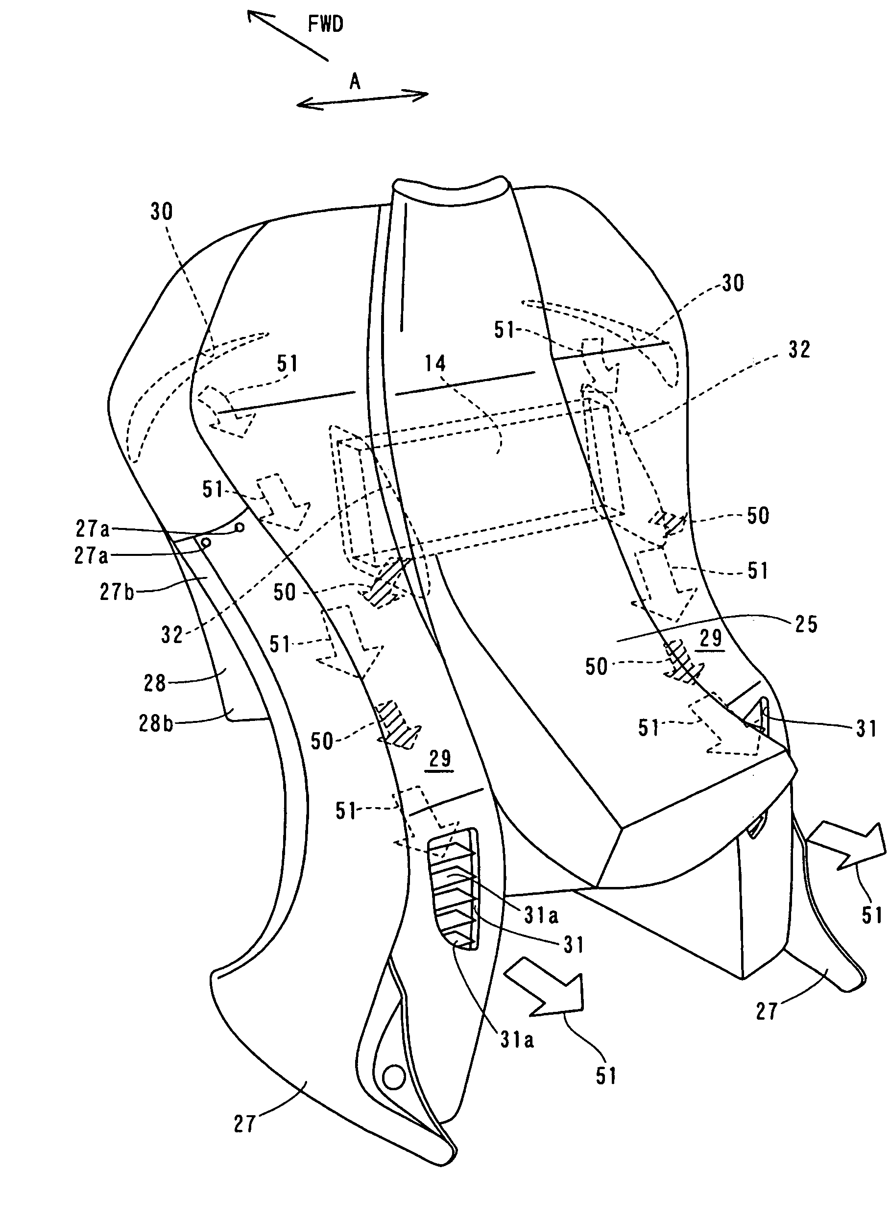
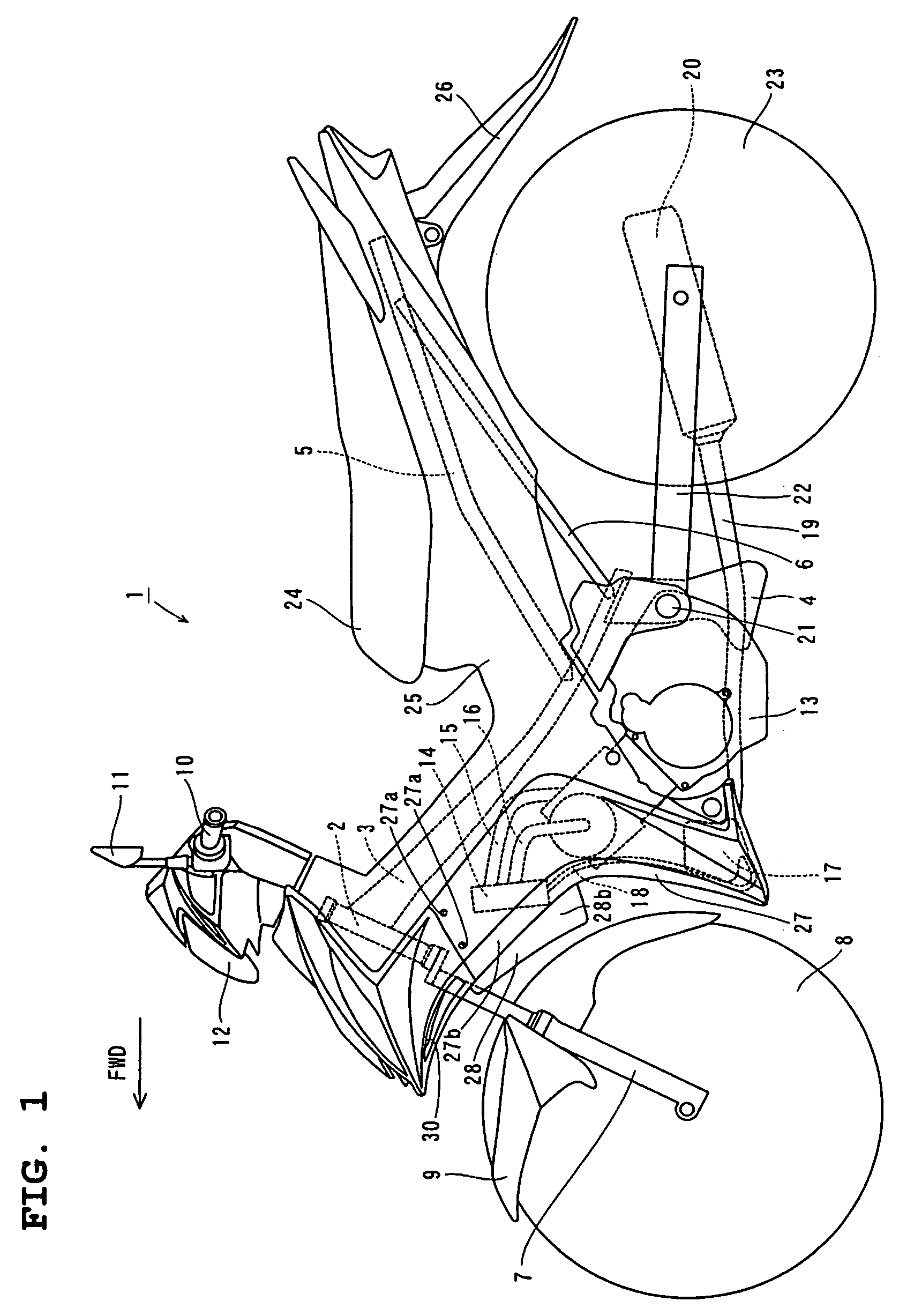
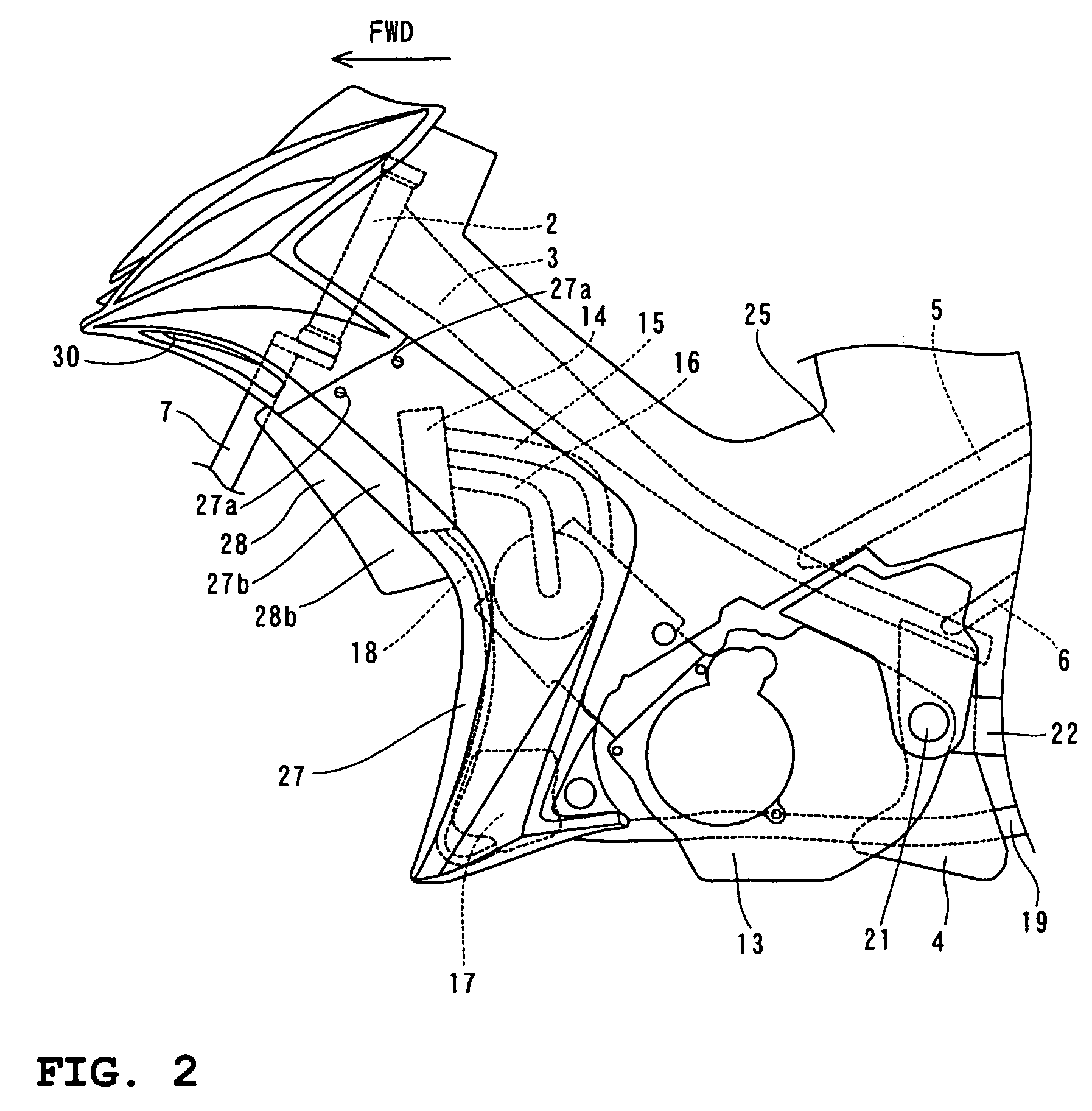
[0030]FIG. 1 is a side elevational view showing the overall structure of a motorcycle according to a preferred embodiment of the present invention. FIG. 2 is an enlarged side elevational view of an engine of the motorcycle according to the preferred embodiment shown in FIG. 1 and also the vicinity of the engine. FIG. 3 is a front elevational view of a leg shield of the motorcycle according to the preferred embodiment shown in FIG. 1 and the vicinity of the leg shield. FIGS. 4-16 are illustrations for describing detailed constructions of the motorcycle according to the preferred embodiment shown in FIG. 1. Additionally, in the figures, reference mark FWD indicates “forward” in a running direction of the motorcycle. Also, in the present preferred embodiment, an under-bone type motorcycle is described as an example of a vehicle in which the frame (main frame) of the motorcycle be...


PUM


Abstract

A vehicle, such as an under-bone type motorcycle, can guide a sufficient amount of running wind to a core section of a radiator (heat exchanger). The vehicle includes a head pipe, a main frame connected to the head pipe to extend downward and rearward, an engine disposed below the main frame, a leg shield covering a front side of a leg of a driver and having an opening in a forward area thereof, a radiator disposed within the opening of the leg shield which includes a core section through which running wind passes thus cooling the engine, and a wind guiding wall attached to the leg shield to guide the running wind to the radiator. The wind guiding wall includes a forward section that protrudes forward from a front end surface of the opening of the leg shield and a rear section that has a rear end positioned adjacent to a lateral side end of the core section of the radiator.

Description

BACKGROUND OF THE INVENTION[0001]1. Field of the Invention[0002]The present invention relates to a vehicle, and particularly relates to a vehicle that has a heat exchanger for cooling an engine.[0003]2. Description of the Related Art[0004]Conventionally, motorcycles having a heat exchanger for cooling an engine are known (for example, see Patent Document JP-A-2002-37166 and Patent Document JP-A-2002-37165).[0005]Patent Document JP-A-2002-37166 discloses a motorcycle having a radiator (heat exchanger) for cooling an engine disposed within a leg shield that covers front sides of the legs of a driver and has an opening in its forward area. In this structure, cooling water of the radiator is considered to be cooled by a portion of running wind introduced through the opening of the leg shield impinging the radiator.[0006]Patent Document JP-A-2002-37165 discloses another motorcycle having a radiator (heat exchanger) for cooling an engine disposed within a leg shield, and a radiator grille...

Claims


Application Information

Patent Timeline
Patent Type & Authority Patents(United States)
IPC IPC(8): B62K11/00B62J99/00
CPCB62J17/02B62K2202/00
Inventor SUNAGUCHI, NAOTOKAMIMURA, KAORUKONNO, TOSHIHIKOMATSUMOTO, YOSHIHARU
Owner YAMAHA MOTOR CO LTD
Why Eureka
Try Eureka