Head vibration detection device and method

a head vibration and detection device technology, applied in the direction of head disposition/mounting, recording information storage, instruments, etc., can solve the problems of head contact asperities, permanent data loss for a write command, and difficulty in distinguishing which head-disc interface is contacting

Inactive Publication Date: 2008-08-12
SEAGATE TECH LLC
View PDF15 Cites 21 Cited by
  • Summary
  • Abstract
  • Description
  • Claims
  • Application Information

AI Technical Summary

Problems solved by technology

Surfaces of the discs include asperities and other defects due to variations in the manufacturing process or created during shipping and handling or operation and use of the disc drive.
During read write operations a head may contact asperities on the disc surface interfering with read / write operations.
Contact between the head and disc surface can damage the disc surface and result in permanent data loss for a write command.
A sensor attached to an E-block arm sense head disc contact for some head on the E-block however its difficult to distinguish which head-disc interface is contacting.

Method used


Image

  • Head vibration detection device and method
  • Head vibration detection device and method
  • Head vibration detection device and method

Examples


Embodiment Construction

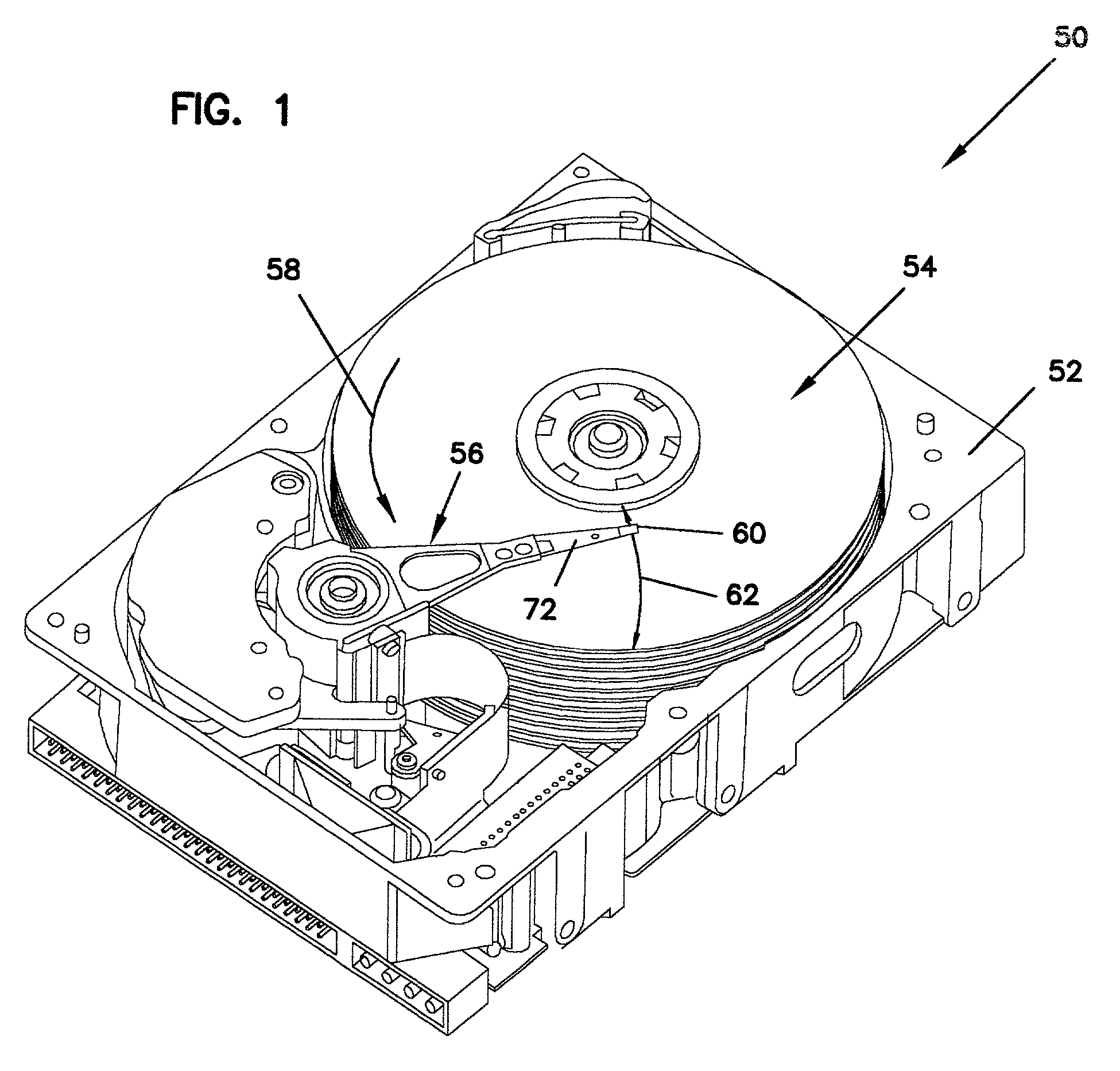
[0017]FIG. 1. illustrates a disc drive 50 including a chassis 52, discs 54, and actuator assembly 56. Discs 54 are rotationally coupled to chassis 52 via a spindle motor (not shown) for rotation, as illustrated by arrow 58. Actuator assembly 56 rotationally supports heads 60 as illustrated by arrow 62 for reading and / or writing data to and from discs 54. Heads include transducer elements supported by a slider. For proximity or near proximity recording the slider flies above the disc surface. Rotation of the disc creates an air flow under an air bearing surface of the slider so that the slider “takes off” from the disc surface. Vibration or shock to the disc drive or asperities in the disc surface can cause the slider to contact or slam into the disc surface during read and write operations. Head disc contact can damage the disc surface and can interfere with a read / write command resulting in permanent data loss for a write command.

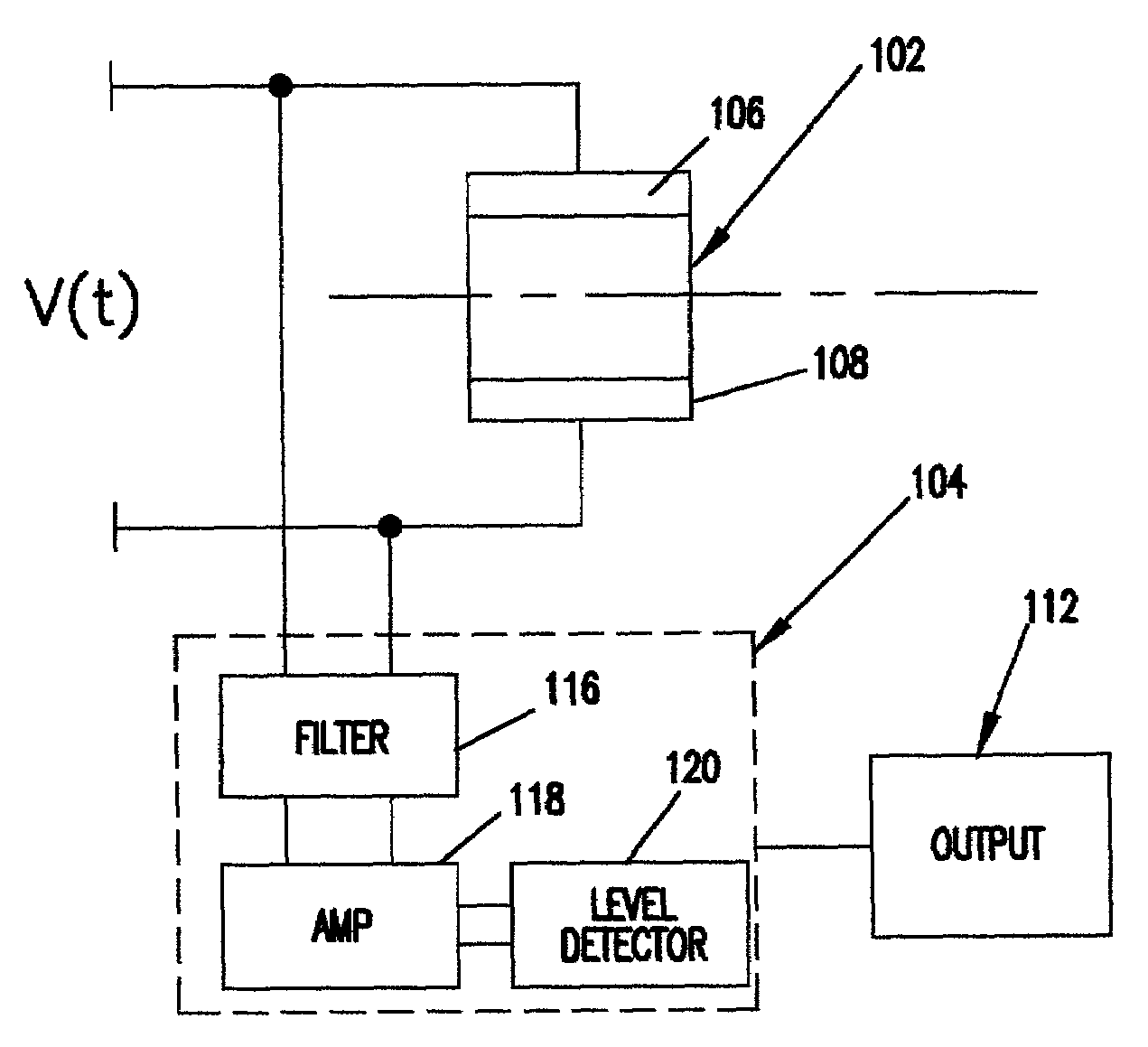
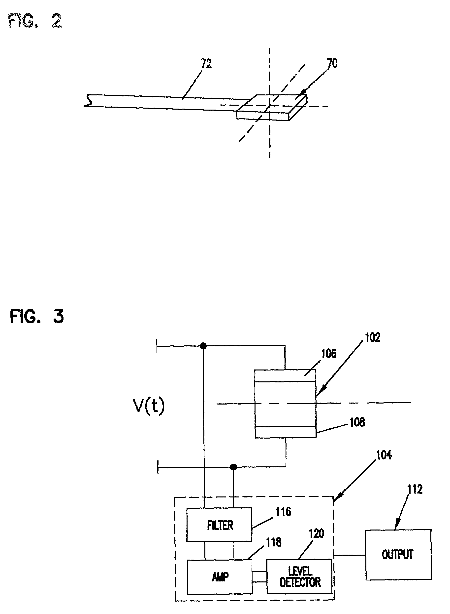
[0018]FIG. 2 diagrammatically illustrates a slider 7...


PUM

PropertyMeasurementUnit
threshold amplitudeaaaaaaaaaa
frequencyaaaaaaaaaa
piezoelectricaaaaaaaaaa

Abstract

A disc drive including a transducer supported on the head suspension assembly to induce a transducer signal in response to head vibration. The transducer signal is level detected to output a level detected signal indicative of head vibration. A method for detecting head vibration via a transducer on a head suspension assembly. The transducer on the head suspension assembly operating between a detection mode and an actuator mode for selectively detecting vibration and actuating the head.

Description

CROSS-REFERENCE TO RELATED APPLICATION[0001]The present application claims priority to U.S. Provisional Application Ser. No. 60 / 121,157, filed Feb. 22, 1999 and entitled “USING A PZT MICROACTUATOR TO SENSE HEAD / DISC CONTACT”.FIELD OF THE INVENTION[0002]The present invention relates to a data storage system. In particular, the present invention relates to an assembly for monitoring head vibration for a data storage system.BACKGROUND OF THE INVENTION[0003]Disc drives are used to store digitally encoded information on discs. Transducer elements read data from and write data to disc supported for rotation by a spindle motor. Transducer elements are supported above the disc surface by a head suspension assembly. Heads are positioned relative to data tracks via a voice coil motor. Disc drive density is increasing necessitating increased head positioning accuracy. Microactuators are used with a voice coil motor for adjusting head position for track placement. Microactuators include piezoel...

Claims


Application Information

Patent Timeline
Patent Type & Authority Patents(United States)
IPC IPC(8): G11B5/02G11B5/012G11B7/09G11B7/12G11B19/04G11B21/02G11B33/08
CPCG11B5/012G11B33/08G11B21/02G11B7/1203G11B7/0946G11B19/04G11B5/5582G11B5/59694G11B7/122
Inventor ANGELO, JAMES E.WRIGHT, JOHN S.
Owner SEAGATE TECH LLC
Why Eureka
Try Eureka