X-ray radiator with thermionic emission of electrons from a laser-irradiated cathode

a technology of laser irradiation and x-ray radiator, which is applied in the direction of x-ray tube cathode assembly, x-ray tube cathode movement, x-ray tube cathode, etc., can solve the problems of soft x-ray radiation, limited use of such an x-ray tube, and insufficient x-ray power, so as to achieve low laser power, simple focusing capability of electron beam, and sufficient x-ray power

Inactive Publication Date: 2008-08-12
SIEMENS HEALTHCARE GMBH
View PDF11 Cites 9 Cited by
  • Summary
  • Abstract
  • Description
  • Claims
  • Application Information

AI Technical Summary

Benefits of technology

[0012]An object of the present invention is to provide an x-ray radiator of the aforementioned type as is used, for example, in medical radiology, in which a sufficient x-ray power can be generated with relatively low laser power; in which a simple focusing capability of the electron beam is possible; and in which a simple and efficient cooling of the system provides good reemployment capability.

Problems solved by technology

This causes problems in the focusing of the electron beam.
Among other things, this problem occurs in the generation of soft x-ray radiation for which a relatively low voltage is applied between the cathode and the anode.
The usage of such an x-ray tube therefore is possible only in a limited manner in specific applications such as, for example, in mammography.
The ability to convert this concept to a practical device appears questionable, however, due to the quantum efficiency of contemporary photo-cathodes and the luminous power required.
With the use of high luminous power, the cooling of the photo-cathode requires a considerable effort due to its rather low heat resilience.
The surface of the photo-cathode is additionally subject to oxidation processes in the vacuum conditions realized in x-ray tubes, which limits the durability of such an x-ray tube.
The longer electron flight path with multiple deflections of the electron beam between the dynodes, requires a high expenditure for focusing the beam.
This appears to be problematic, however, with regard to the luminous power then required.

Method used


Image

  • X-ray radiator with thermionic emission of electrons from a laser-irradiated cathode
  • X-ray radiator with thermionic emission of electrons from a laser-irradiated cathode
  • X-ray radiator with thermionic emission of electrons from a laser-irradiated cathode

Examples


Embodiment Construction

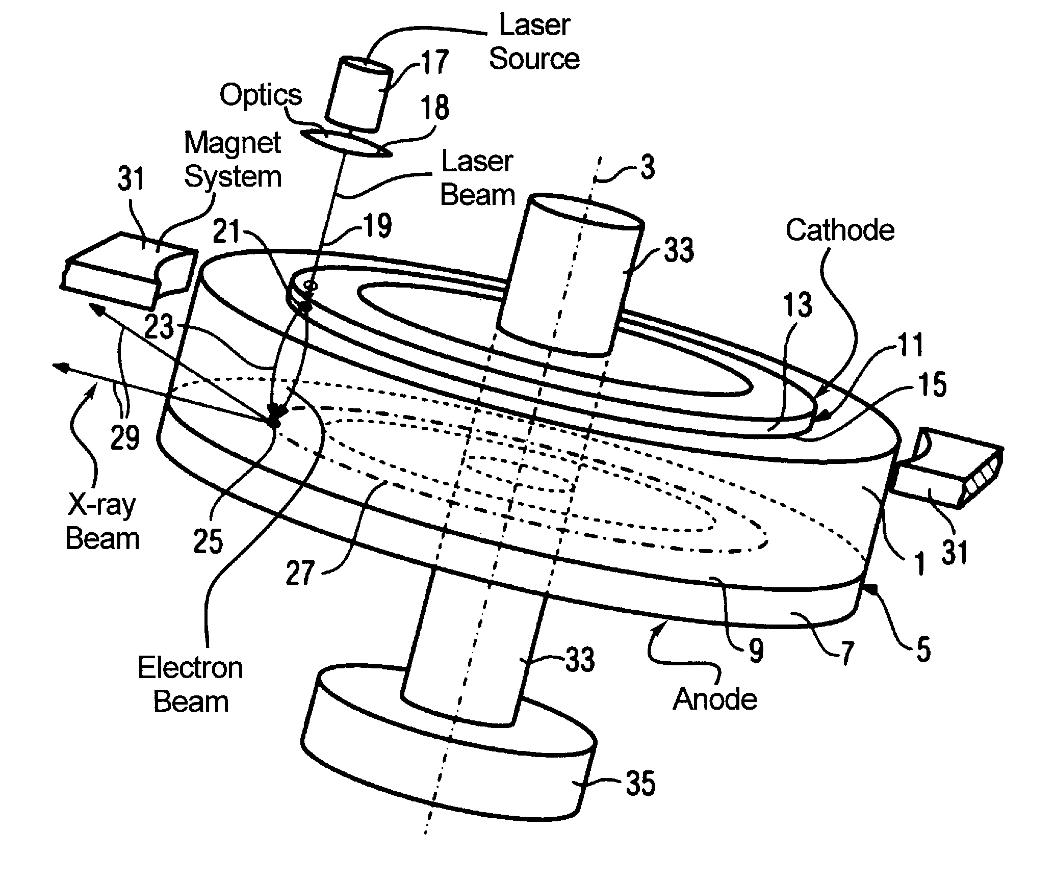
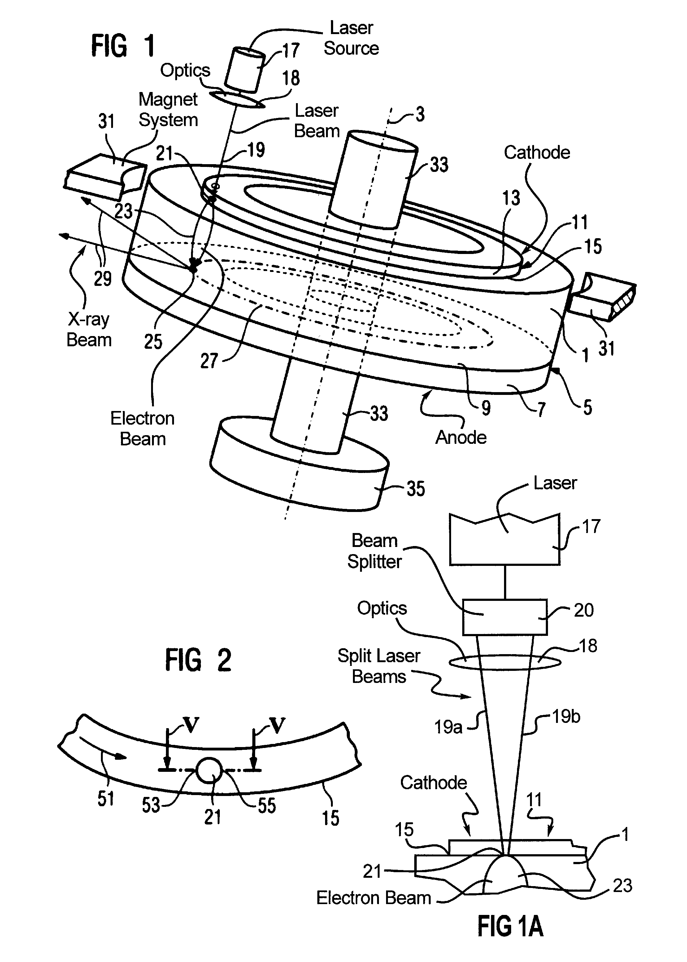
[0039]A three-dimensional representation of a vacuum housing 1 is shown in FIG. 1. The vacuum housing 1 is fashioned as a cylinder in which the cylinder casing is formed by an insulating material, and the vacuum housing 1 is supported rotationally symmetrically around an axle 3. An anode 5 forms the base of the cylinder. The anode has a support layer 7 and an annularly-fashioned surface 9 from which x-rays 29 are emitted. Located in the oppositely-situated base of the vacuum housing 1 (cylinder) is an annularly-fashioned cathode 11. It has a support layer 13 that is part of the outside of the vacuum housing 1 and a surface 15 faces the inside of the vacuum housing 1.

[0040]The anode 5 and cathode 11 shown here are fashioned axially symmetric. However, it can also be advantageous to fashion the anode 5 and the cathode 11 (in particular their support layers 7, 13) such that they exhibit only a discrete axial symmetry. The means a segment-by-segment design of the cathode 11 or of the an...


PUM


Abstract

An x-ray radiator has a vacuum housing that can rotate around an axis, a cathode that thermionically emits electrons upon irradiation thereof by a laser beam, an anode that emits x-rays upon being struck by the electrons, an insulator that is part of the vacuum housing and that separates the cathode from the anode, electrodes or terminals to apply a high voltage between the anode and the cathode to accelerate the emitted electrons toward the anode to form an electron beam, a drive arrangement for rotation of the vacuum housing around its axis, an arrangement for cooling components of the x-ray radiator, and an arrangement that directs and focuses the laser beam from a stationary source that is arranged outside of the vacuum housing onto a spatially stationary laser focal spot on the cathode.

Description

BACKGROUND OF THE INVENTION[0001]1. Field of the Invention[0002]The present invention concerns an x-ray radiator with an evacuated housing supported for rotation around a rotation axle, in which housing are arranged a cathode and an anode, whereby the cathode having a surface that emits electrons upon laser irradiation, and having a drive arrangement to rotate the housing.[0003]2. Description or the Prior Art[0004]High-power x-ray radiators typically have an anode that is supported such that it can rotate in order to ensure a high thermal resilience of the anode even during generation of x-rays with high radiated power.[0005]DE 87 13 042 U1 describes an x-ray tube with an evacuated housing supported such that it can rotate around a rotation axis, in which are arranged a cathode and an anode. The cathode and the anode are permanently connected with the housing. The x-ray tube has a drive arrangement to rotate the housing around the rotation axis. A deflection system that is stationar...

Claims


Application Information

Patent Timeline
Patent Type & Authority Patents(United States)
IPC IPC(8): H01J35/06
CPCH01J35/065H01J35/16H01J35/26H01J35/305H01J2235/162H01J2235/066H01J2235/068H01J2235/1006H01J2235/062
Inventor FREUDENBERGER, JORGFRITZLER, SVENFUCHS, MANFREDMATTERN, DETLEFROHRER, PETERSCHARDT, PETER
Owner SIEMENS HEALTHCARE GMBH
Why Eureka
Try Eureka