Key blank and key

Active Publication Date: 2008-08-19
ASSA ABLOY HIGH SECURITY GRP INC
View PDF34 Cites 10 Cited by
  • Summary
  • Abstract
  • Description
  • Claims
  • Application Information

AI Technical Summary

Benefits of technology

[0019]This invention provides specific parameters for key section profiles and the corresponding key ways in a cylinder plug that allows for the development of many exclusive and non-interchangeable hierarchical master key systems. In order to accomplish this, the key blade is considered separately for three vertical sections from the bottom edge of the blade up to the bitting surface edge of the blade. Each of the three sections is contoured or formed with specific variations of ridges and grooves that establish the key blank's position within a hierarchical system or systems. The bottom most section has a registry groove for the positioning of any secondary side milling operations used in the manufacture of the blank. This registry groove also allows for exact positioning of the blank in a key cutting or bitting machine. A second vertical section of the blade has at least one undercut longitudinal groove on at least one side of the blade. The location and shape of the undercut groove in the second section determines the primary family of the hierarchical system. The third section of the blade, just below the bitting surface may be divided vertically into two sides. One of these sides has a variation of the key section p

Problems solved by technology

Keys using an undercut groove profile require additional form cutting on specially designed machines that are usually not available at commercial duplicator operations and thus the blanks are more difficult to copy or counterfeit.
This increases the system size of pin tumbler cylinders.
In addition it provides a narrow cross sectional width under the bitting area, thus making it difficult to

Method used


Image

  • Key blank and key
  • Key blank and key
  • Key blank and key

Examples


Embodiment Construction

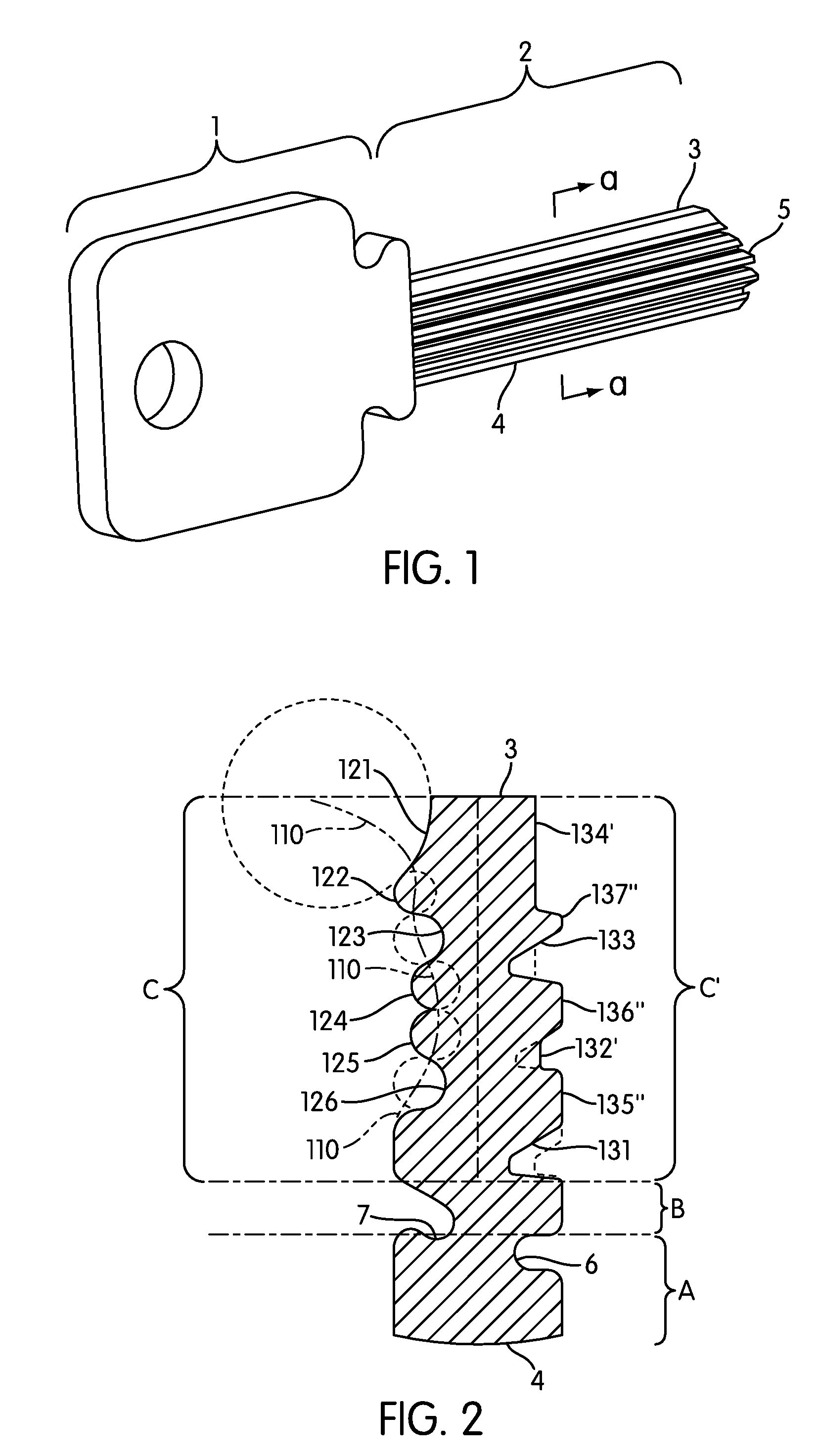
[0024]FIG. 1 shows a prospective view of a key blank according to this invention. The key blank has a head or bow 1 for holding and turning the key and a blade 2 for inserting into a keyway of a lock cylinder. The keyway of the lock cylinder has a profile matching the profile of the key blade. The key blade has a top surface 3 into which key bittings (not shown) are cut to position elements such as pin tumblers in a lock cylinder as is well known in the art, see for example the patent to Medeco Security Locks U.S. Pat. No. 5,419,168. The blank has a bottom surface 4 and an end tip 5. The end tip 5 may have a stop or other configuration; see for example U.S. Pat. No. 1,679,558.

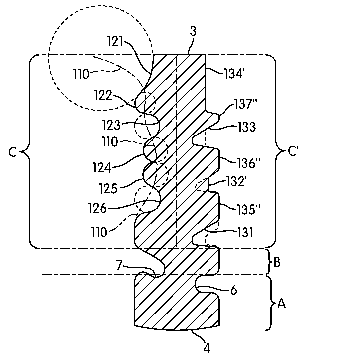
[0025]The cross section of the key blank in one configuration is shown in FIG. 2. FIG. 2 shows the top of the key blank blade 3 and the bottom of the key blank blade 4 and as shown in phantom lines three different sections. Section A, B, C and C′. As shown, Section A is adjacent to the bottom of the blade, Sect...


PUM


Abstract

A key blank or key has a rectangular parallel metal shaped blade which has side edges formed with grooves for cooperating with a complementary shaped keyway; the sides of the blank having a portion grooved for registration, another portion grooved for top-level hierarchical master keying, and two other portions, one on each side of the blade, for further master key variations and different combinations. One of the two further sections being curvilinear and the other rectangular or angular cuts.

Description

[0001]This invention relates to improvements in keys and key blanks, particularly with regard to defining the profiles of keys and key blanks using the shapes of ridges or grooves in a generally flat rectangular key blade profile. The shape of the key blank and key, of course, determines the shape of the keyway in a lock cylinder plug.BACKGROUND AND PRIOR ART[0002]The lock cylinders art is requiring higher and higher security and there is a need in the art for the development of a shape or profile of a cross section of key and corresponding shape of the keyway in the cylinder plug to accommodate a hierarchical lock providing high security. The shape of the keyway is the first barrier that rejects or filters an unauthorized key in attempt to operate the lock cylinder.[0003]There is only a finite space in a lock cylinder plug that can be occupied by the key and that space must be structured to allow for the maximum number of unique keyway shapes to be able to develop lock systems of a...

Claims


Application Information

Patent Timeline
IPC IPC(8): E05B19/06
CPCE05B27/0053E05B19/0029Y10T70/7864Y10T70/8595Y10T70/7881Y10T70/7503Y10T70/7938Y10T70/7463Y10T70/787E05B19/00E05B27/00
Inventor FIELD, PETER H.POFF, STEVE
Owner ASSA ABLOY HIGH SECURITY GRP INC
Why Eureka
Try Eureka