
Device for determination and/or monitoring of the volumetric and/or mass flow of a medium and having coupling element including two element portions

a technology of volumetric and/or mass flow and measuring device, which is applied in the direction of volume/mass flow by dynamic fluid flow effect, measurement device, instruments, etc., can solve the problems of unfavorable measurement accuracy, limited use of ultrasonic flow measuring device using the doppler principle, and relatively complex embodiment. , to achieve the effect of strong temperature dependen

Active Publication Date: 2008-08-19
ENDRESS HAUSER FLOWTEC AG
View PDF12 Cites 15 Cited by
  • Summary
  • Abstract
  • Description
  • Claims
  • Application Information

AI Technical Summary

Benefits of technology

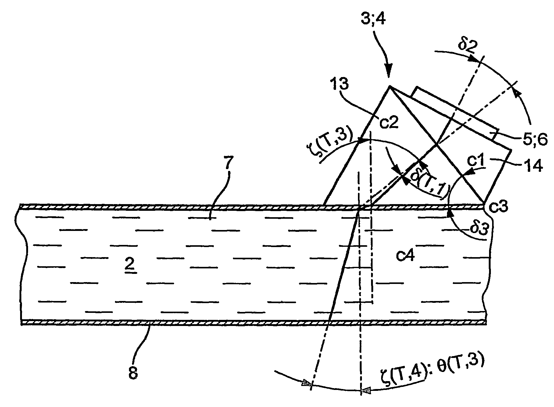
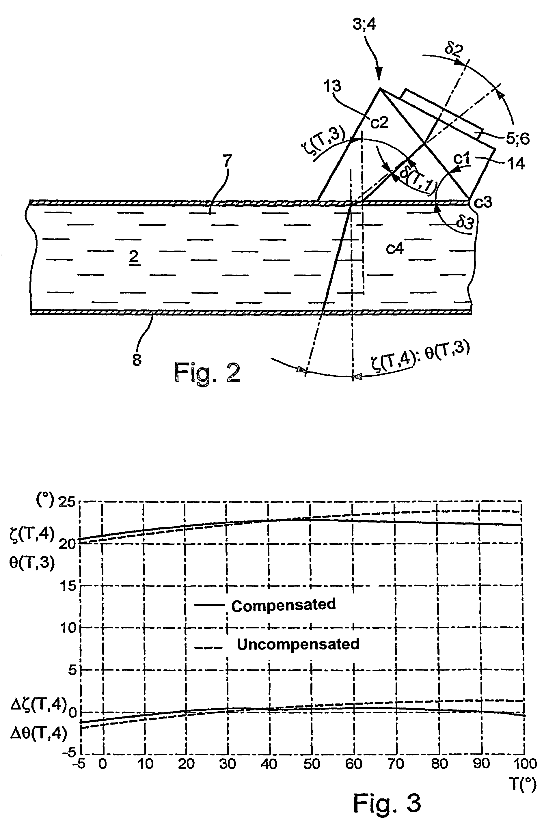
[0022]With this embodiment, the influence of temperature fluctuations of the medium on the in-coupling, or out-coupling, angle can be directly eliminated, or the effects can be kept so small, that the measurement accuracy is only insignificantly degraded.
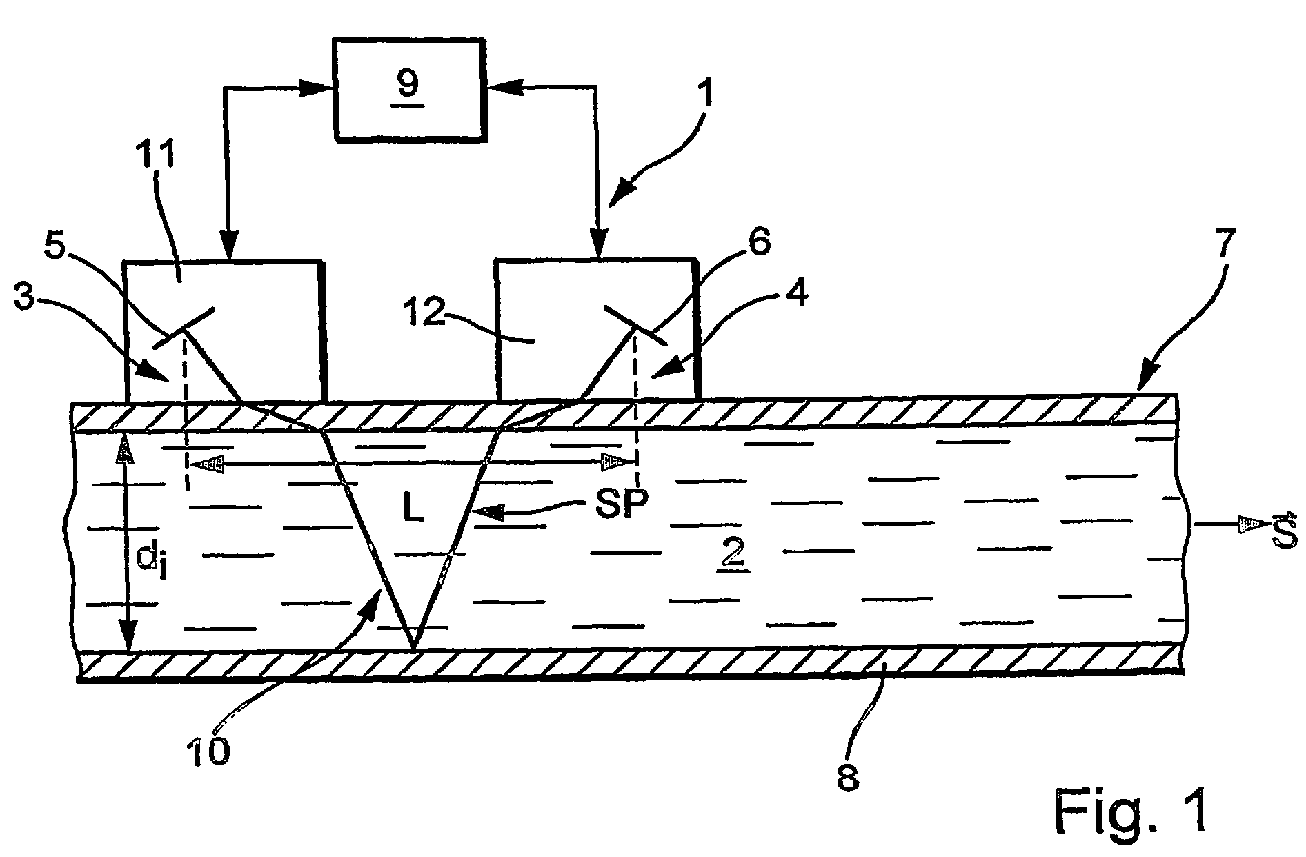
[0023]In an advantageous embodiment of the apparatus of the invention, it is provided that the path lengths, which the ultrasonic measuring signals trace in the element portions of the coupling wedges, or the lead-in members, are so selected, that the sum of the corresponding travel times, which the ultrasonic measuring signals require for traversing the element portions, is at least approximately constant over a predetermined temperature range. This is achieved preferably by the appropriately selected dimensioning of the element portions. This embodiment assures that, almost independently of temperature changes, always the maximum signal amplitude of an ultrasonic measuring signal is received from each ultrasonic transducer. More or less complex readjustments of the ultrasonic transducers on the pipe due to temperature changes in the sensors are, consequently, not required.

Problems solved by technology

Thus, use of ultrasonic flow measuring devices using the Doppler principle is rather limited, compared to ultrasonic flow measuring devices using the travel-time-difference principle.
Both changes, in the case of an ultrasonic flow measuring device operating according to the travel time difference method, naturally act unfavorably on the accuracy of measurement.
This embodiment is, however, relatively complex.

Method used


Image

  • Device for determination and/or monitoring of the volumetric and/or mass flow of a medium and having coupling element including two element portions
  • Device for determination and/or monitoring of the volumetric and/or mass flow of a medium and having coupling element including two element portions
  • Device for determination and/or monitoring of the volumetric and/or mass flow of a medium and having coupling element including two element portions

Examples


Embodiment Construction

[0019]In a preferred embodiment of the apparatus of the invention, the coupling element comprises at least two coupling wedges, which are successively traversed by the ultrasonic measuring signals. Preferably, the coupling wedges are made of plastics with different sound velocities.

[0020]The element portions, or the coupling wedges, as the case may be, comprise, in an advantageous embodiment of the apparatus of the invention, different materials, with the materials being selected such that temperature-related changes of sound velocity, or the index of refraction, of a first element portion, or a first coupling element, as the case may be, are at least approximately compensated by temperature-related changes of sound velocity, or index of refraction, of at least a second element portion, or a second coupling wedge, as the case may be. Preferably, the compensation occurs over as great a temperature range as possible.

[0021]In an alternative embodiment of the apparatus of the invention,...


PUM


Abstract

A clamp-on ultrasonic flow measuring device for determining volume and / or mass flow rate of a medium in a containment. The clamp-on ultrasonic measuring device is of low temperature sensitivity. To this end, the coupling element, through which the ultrasonic measuring signals are coupled into, and / or out of, the containment, has at least two element portions, which are embodied and / or arranged in such a manner that the predetermined in-coupling angle into the containment and / or the predetermined out-coupling angle out of the containment are / is approximately constant over an extended temperature range.

Description

FIELD OF THE INVENTION[0001]The invention relates to an apparatus for determining and / or monitoring the volume and / or mass flow rate of a medium in a containment, especially in a pipe. The apparatus includes: at least one ultrasonic transducer, which emits and / or receives ultrasonic measuring signals; associated with the ultrasonic transducer, a coupling element, via which the ultrasonic measuring signals are coupled into, and out of, the containment at a predetermined in-coupling / out-coupling angle; and a control / evaluation unit, which, on the basis of the measuring signals, or on the basis of measurement data derived from the measuring signals, determines the volume and / or mass flow rate of the medium flowing in the containment.BACKGROUND OF THE INVENTION[0002]Ultrasonic flow measuring devices are applied often in process and automation technology. They make possible contactless determination of the volume and / or mass flow rate of a medium in a pipeline.[0003]Known ultrasonic flow...

Claims


Application Information

Patent Timeline
Patent Type & Authority Patents(United States)
IPC IPC(8): G01F1/66G01F15/02
CPCG01F1/662G01F15/02G01N2291/02836
Inventor WIEST, ACHIMBERGER, ANDREASSTRUNZ, TORSTEN
Owner ENDRESS HAUSER FLOWTEC AG
Learn More