Radio device and method of calibration of antenna directivity
a radio device and directivity technology, applied in power management, transmission monitoring, receiver monitoring, etc., can solve the problems of transmission characteristics of transmit signals changing, transmit signals cannot be flown toward the target, and transmission/receiving of radio signals cannot be performed with excellent directivity between the targeted user
- Summary
- Abstract
- Description
- Claims
- Application Information
AI Technical Summary
Benefits of technology
Problems solved by technology
Method used
Image
Examples
embodiment 1
[0189]FIG. 6 is a flow chart showing correction value calculation processing according to an embodiment 1 of the present invention.
[0190]First, start of correction value calculation is instructed by the processor 100 (step S1).
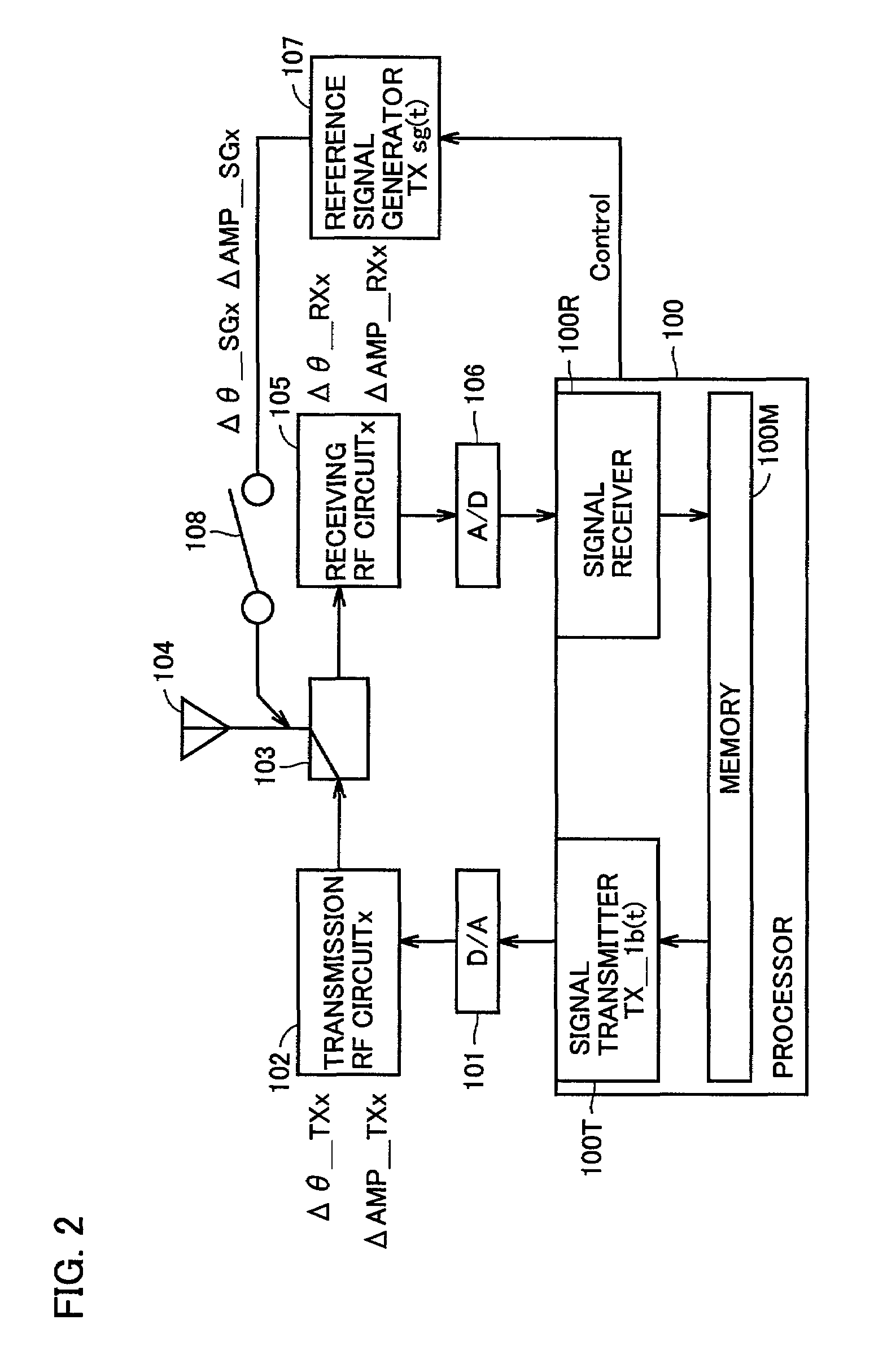
[0191]The connective relation (FIG. 3) of the aforementioned loop back mode is executed under control of the processor 100, and a signal is transmitted from the signal transmitter 100T and the D / A converter 101 (step S2).
[0192]The transmitted signal passes through both of the “transmission circuit” and the “receiving circuit” in the loop back mode, and is received in the A / D converter 106 and the signal receiver 100R (step S3).
[0193]The processor 100 calculates the quantity of phase rotation (equation (3)) and the quantity of amplitude fluctuation (equation (4)) of the signal received through the loop back mode by the aforementioned [procedure 2] and stores the same in the memory 100M (step S4).
[0194]Then, the connective relation (FIG. 5) of the aforementioned...
embodiment 2
[0200]FIG. 7 is a flow chart showing correction value calculation processing according to an embodiment 2 of the present invention.
[0201]There may be a case where correct quantity of phase rotation and quantity of amplitude fluctuation of a receive signal are not necessarily obtainable when performing measurement once in the loop back mode and once in the reference signal receiving mode as the embodiment 1 of FIG. 6. Therefore, it is conceivable to perform measurement by an arbitrarily set number of times (about 4 to 10 times, for example) in both of the loop back mode and the reference signal receiving mode for performing calculation of the quantity of phase rotation and the quantity of amplitude fluctuation of the receive signal after averaging the results thereof, in order to attain improvement of measurement accuracy.
[0202]When correction value calculation start is instructed (step S11), a variable I is set to zero (step S12), and it is determined that I=0 does not reach a presc...
embodiment 3
[0210]FIG. 8 is a flow chart showing correction value calculation processing according to an embodiment 3 of the present invention.
[0211]In general, there is such a tendency that characteristics of phases and amplitudes of amplifiers, filters, mixers etc. included in a “transmission circuit” and a “receiving circuit” change depending on the frequency of a transmit signal.
[0212]In order to improve accuracy of measurement of the correction values, therefore, it is desirable to perform measurement in the loop back mode and measurement in the reference signal receiving mode in the respective ones of a plurality of transmission frequencies and to calculate correction values for the respective ones of the plurality of transmission frequencies.
[0213]When calculation start for the correction values is instructed by the processor 100 (step S31), a desired transmission frequency f1 is first set (step S32) in the embodiment 3 of FIG. 8. Thereafter steps S33 to S39 which are the same processing...
PUM
 Abstract
Description
Claims
Application Information
 - R&D
- Intellectual Property
- Life Sciences
- Materials
- Tech Scout
- Unparalleled Data Quality
- Higher Quality Content
- 60% Fewer Hallucinations
Browse by: Latest US Patents, China's latest patents, Technical Efficacy Thesaurus, Application Domain, Technology Topic, Popular Technical Reports.
© 2025 PatSnap. All rights reserved.Legal|Privacy policy|Modern Slavery Act Transparency Statement|Sitemap|About US| Contact US: help@patsnap.com


