
Method and arrangement for counteracting inappropriate manual gearshifts in predetermined vehicle conditions

a technology of manual gearshift and predetermined vehicle conditions, which is applied in the direction of gearing control, gearing element, belt/chain/gearing, etc., can solve the problems of engine rotation speed falling, engine cannot drive the vehicle without stalling, etc., to prevent gear shifting inappropriate for certain vehicle conditions, the effect of less expensive and cost-effectiv

Inactive Publication Date: 2008-08-19
VOLVO TRUCK CORP
View PDF8 Cites 9 Cited by
  • Summary
  • Abstract
  • Description
  • Claims
  • Application Information

AI Technical Summary

Benefits of technology

The method effectively prevents inappropriate gear shifts, reducing the risk of engine stalling and damage while improving driver ergonomics and safety by making inappropriate gear shifts more noticeable through increased sluggishness in the gearshift control.

Problems solved by technology

When the vehicle is underway, however, certain gears may be considered inappropriate under the prevailing operating conditions.
This can result in the rotational speed of the engine falling to such a level that the engine is incapable of driving the vehicle without stalling.
Under other conditions the engagement of inappropriate gears may be damaging and dangerous.
Such engagement can result in a very high rotational speed of the transmission input shaft.
Moreover, if the geared coupling arrangement, which is used in engaging the gear in question, is provided with a synchromesh arrangement of known type, this is exposed to a very high stress when the input shaft is accelerated to said very high rotational speed.
However, a separate arrangement for preventing the engagement of inappropriate gears is generally not provided on simpler types of manual transmissions, like those used in smaller vehicles such as passenger cars and smaller trucks.
When trying to engage a low gear at high vehicle speeds, for example, the time for synchronization, that is to say acceleration of the input shaft, is so long that the driver generally manages to perceive that it is inappropriate and can discontinue the gearshift.
This would result in a very high rotational speed on the input shaft.
This is because the synchromesh arrangements in the geared coupling arrangement of the range transmission would otherwise be overloaded or would have to have absurdly large dimensions.
This prevents the engagement of a number of the gears in the basic transmission when, according to predefined rules, this is inappropriate under the prevailing operating conditions.
One disadvantage of the mis-shift counteracting arrangements according to and is that the pneumatic cylinder with associated parts increases the manufacturing cost of the transmission.
This can lead to serious space problems in the driver's cab with the risk of the gearshift control catching on the driver's seat or the instrument panel.
An even greater disadvantage is that the positions for certain gears end up a long way from the driver.
When these gears are to be engaged, this results in a non-ergonomic working position for the driver.
The result is low possible shifting forces and a risk of damage due to wear.
A major disadvantage with this system is that in practice it has proved difficult to always determine clearly which gear in the range transmission the driver wishes to engage.
For certain combinations of vehicle, engine and transmission it can be difficult, given certain combinations of engine speed, vehicle speed and gearshift control movement, to decide whether the driver wishes to shift to low-range gears or to high-range gears.
However, the embodiments hitherto demonstrated have required a separate mis-shift counteracting arrangement, which has a disadvantage in terms of cost.
One disadvantage, on the other hand, is that the low forces on the gearshift control in conjunction with the large overall shifting forces make it more difficult for the driver to discover in good time any inappropriate gearshift of the type described earlier.
Another disadvantage, which is relevant in trucks, for example, is the risk of the driver accidentally knocking against the gearshift control, for example when moving between the driver's seat and the sleeping space in the driver's cab.
If, in so doing, a gear is engaged, the vehicle can be set in motion, which can constitute a safety risk.
Reducing the shifting force supplied by the shift servo means that the driver will experience an increased sluggishness in the gearshift control.
From information supplied on the vehicle condition and preprogrammed information on inappropriate gearshifts in various vehicle conditions, a control unit can very easily interrupt the energy supply to the shift servo.

Method used


Image

  • Method and arrangement for counteracting inappropriate manual gearshifts in predetermined vehicle conditions
  • Method and arrangement for counteracting inappropriate manual gearshifts in predetermined vehicle conditions
  • Method and arrangement for counteracting inappropriate manual gearshifts in predetermined vehicle conditions

Examples


Embodiment Construction

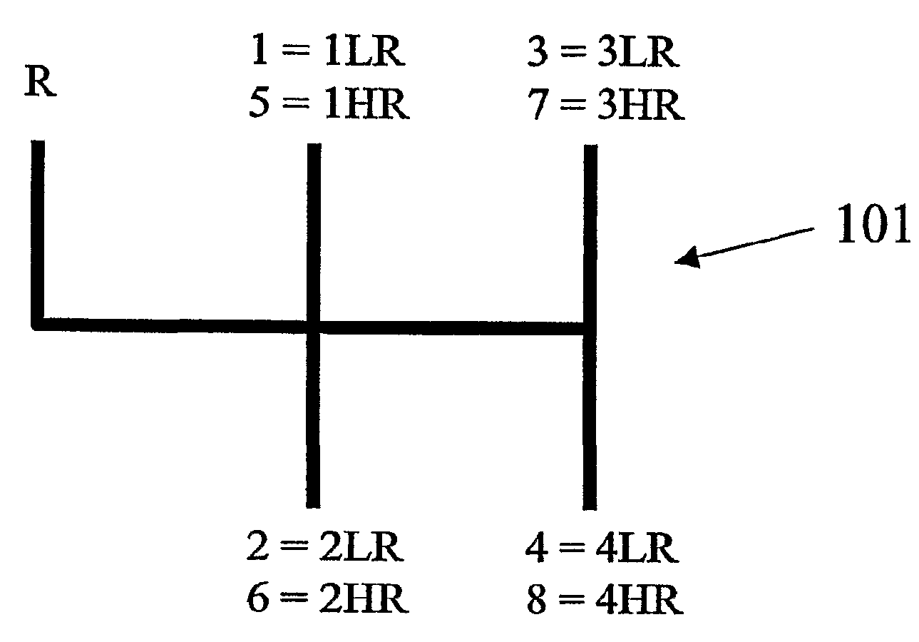
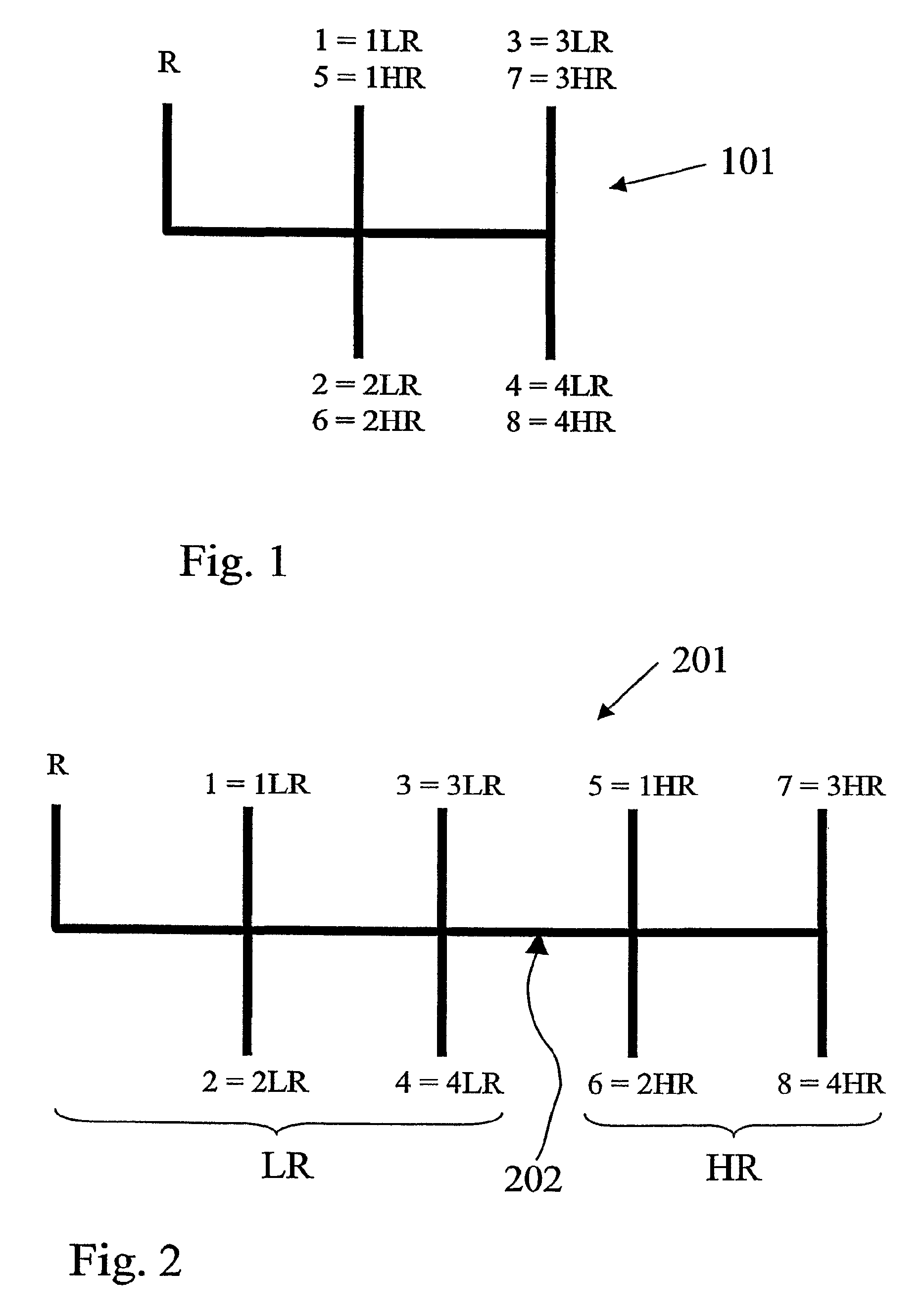
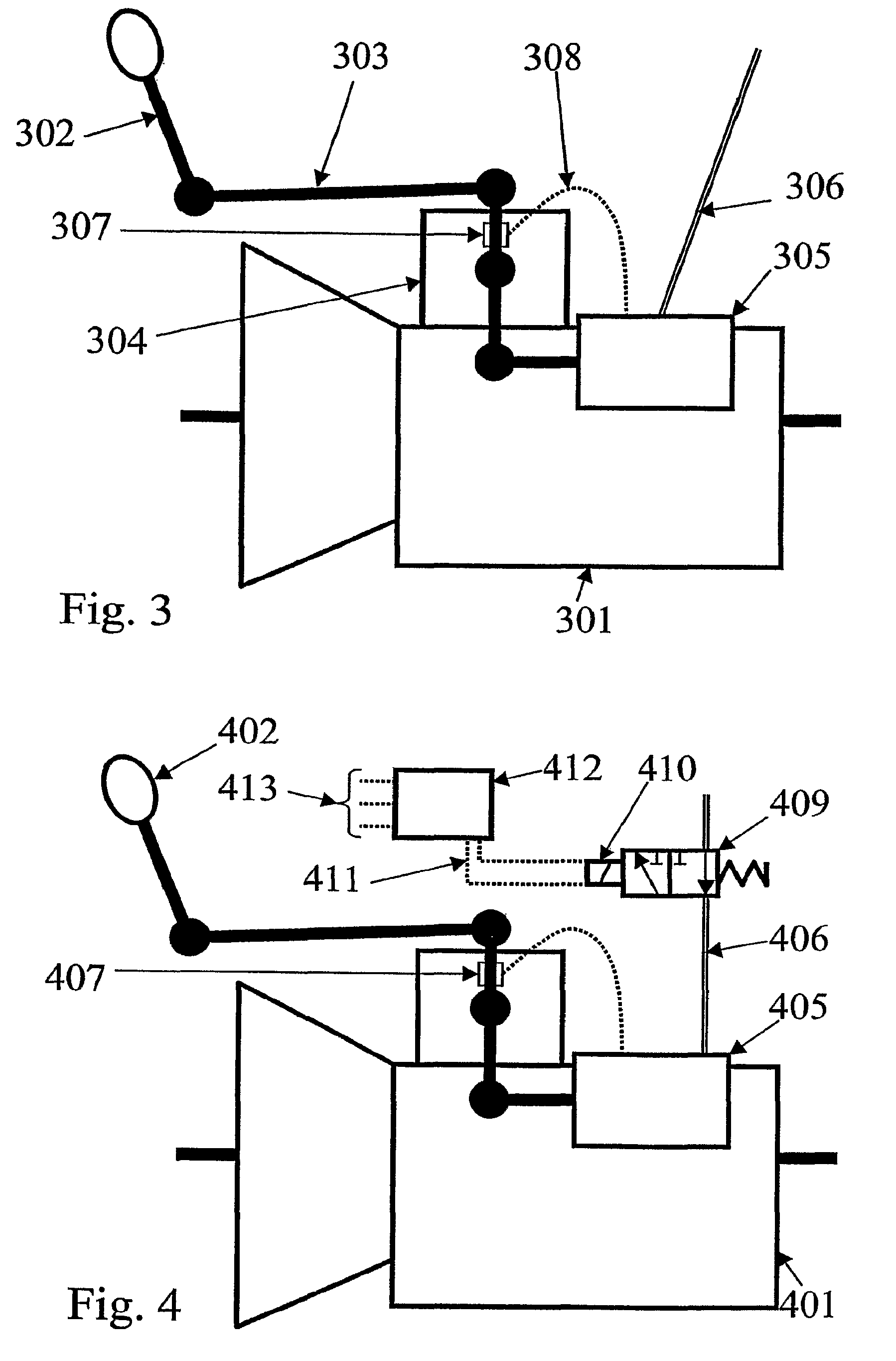
[0036]A simple way of obtaining a mis-shift counteracting arrangement on a manual transmission, which is provided with a shift servo, is to substantially reduce, in accordance with predefined rules, the additional shifting force supplied by the shift servo for inappropriate gearshifts. For electronically controlled shift servos this is relatively easy to achieve without additional components-The additional force which the shift servo delivers can then be set to a low level, or alternatively to a negative level, which means that the shift servo imparts an action opposed to the shifting force applied by the driver. Exemplary embodiments of this will be seen from FIGS. 5 and 6.

[0037]Pneumatic and hydraulic shift servos, however, are generally not as easy to control. According to an advantageous embodiment of the invention the additional force supplied by the shift servo is reduced by restricting or interrupting the energy supply to the shift servo. This is represented schematically in ...


PUM


Abstract

The invention relates to a method and an arrangement for counteracting inappropriate manual gearshifts in predetermined vehicle conditions by way of a gearshift control in a stage-geared transmission, arranged in a motor vehicle and having a shift servo for intensifying the shifting force applied to the gearshift control. In the case of a pneumatic or hydraulic shift servo the control unit is designed to interrupt the energy supply to the shift servo by closing a valve. The shifting force applied to the gearshift control can be measured, the level of the output force from the shift servo being determined as a function of the measured shifting force applied.

Description

BACKGROUND AND SUMMARY[0001]The present application is a continuation of International Application No. PCT / SE2005 / 000073, filed Jan. 21, 2005, which claims priority to SE 0400192-1, filed Jan. 30, 2004. The present invention relates to a method for counteracting inappropriate manual gearshifts in predetermined vehicle conditions by way of a gearshift control in a stage-geared transmission, arranged in a motor vehicle and having a shift servo for intensifying the shifting force applied to the gearshift control.[0002]The present invention also relates to a motor vehicle stage-geared transmission, the input shaft of which is coupled to an engine arranged in the vehicle for propelling the vehicle by way of a clutch for isolating the engine from the transmission. The transmission comprises a gearshift control for manual gear selection, a sensor arrangement for detecting the shifting force applied to the gearshift control, a shift servo controlled by the sensor arrangement for amplifying ...

Claims


Application Information

Patent Timeline
Patent Type & Authority Patents(United States)
IPC IPC(8): F16H59/00F16HF16H61/16F16H61/18F16H61/30F16H61/70
CPCF16H61/18F16H61/30Y10T74/19251F16H61/70
Inventor HEDMAN
Owner VOLVO TRUCK CORP
Learn More