Reaction apparatus and mixing system

a technology of reaction apparatus and mixing system, which is applied in the direction of gas-gas reaction process, furnace, instruments, etc., can solve the problems of slow gas/liquid mixing, unstable gas/liquid mixing ratio, and inability to obtain etc., to achieve stable gas/liquid mixing ratio, increase reaction rate, and easy replacement of mixing apparatus

Inactive Publication Date: 2008-08-19
HITACHI LTD
View PDF7 Cites 3 Cited by
  • Summary
  • Abstract
  • Description
  • Claims
  • Application Information

AI Technical Summary

Benefits of technology

[0006]This invention intends to provide a reaction apparatus capable of obtaining a stable gas / liquid mixing ratio and increasing the reaction rate.
[0007]This invention further intends to provide a mixing system capable of easily replacing a mixing apparatus in a case where troubles occur in the mixing apparatus or for obtaining necessary products, and capable of obtaining a stable mixing ratio and increasing the mixing speed.

Problems solved by technology

However, in the existent gas / liquid mixing and dissolving apparatus described above, since the gas / liquid mixture is formed by stirring and mixing the gas pressurized by the compressor to the liquid pressurized by the pump, the gas / liquid mixture is jetted into the dissolution tank to generate the turbulent vortexes of bubbles, inside the dissolution tank and make the bubbles formed inside the dissolution tank finer, bubbles of not uniform size are formed.
This results in a problem that no stable gas / liquid mixing ratio can be obtained in the gas / liquid mixing and dissolving apparatus and the gas / liquid mixing is slow.

Method used


Image

  • Reaction apparatus and mixing system
  • Reaction apparatus and mixing system
  • Reaction apparatus and mixing system

Examples


first embodiment

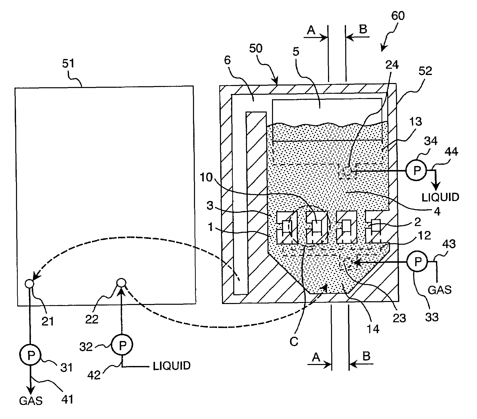
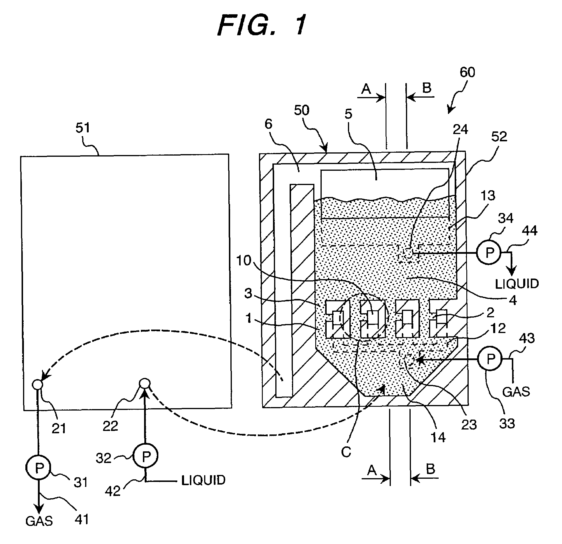
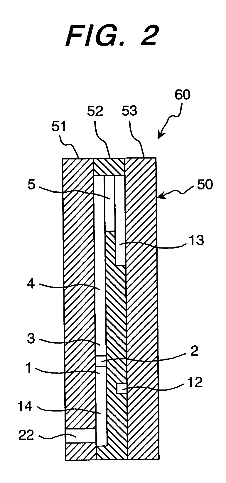
[0027]A reaction apparatus of a first embodiment according to this invention is to be described with reference to FIG. 1 to FIG. 4.

[0028]At first, a constitution of the reaction apparatus of this embodiment is to be explained.

[0029]A reaction apparatus 60 comprises an apparatus main body 50, pumps 31 to 34 and pipelines 41 to 44. The apparatus main body 50 constitutes a main portion of the reaction apparatus 60. The pumps 31 to 34 are disposed for supplying or discharging a liquid or a gas to and from the apparatus main body 60. A control device (not illustrated) controls, for example, the on-off operations and the number of rotation of the pumps 31 to 34. The pipelines 41 to 44 are constituted so as to connect the outside of the apparatus with each of the communication ports of the apparatus main body 50 by way of the pumps 31 to 34.

[0030]The pump 32 and the pipeline 42 are disposed as a pressurization device for supplying a liquid under pressure from the outside of the apparatus t...

seventh embodiment

[0114]Then, a reaction apparatus of a seventh embodiment according to this invention is to be described with reference to FIG. 14 and FIG. 15.

[0115]FIG. 14 is a cross sectional view showing a reaction apparatus main body of the seventh embodiment according to this invention, corresponding to line A-A in FIG. 1. FIG. 15 is a cross sectional view showing a reaction apparatus main body of the seventh embodiment according to this invention corresponding to line B-B in FIG. 1.

[0116]The seventh embodiment is basically identical with the first embodiment but is different for the following points. In the seventh embodiment, the liquid discharge flow channel 13 and the liquid discharge port 24 in the first embodiment are a gas discharge flow channel 13 and a gas discharge port 24, while the gas discharge flow channel 6 in the first embodiment is a liquid discharge flow channel 6. Then, the liquid communication flow channel 5 disposed between the bubble reaction flow channel 4 and the gas dis...


PUM

PropertyMeasurementUnit
depthaaaaaaaaaa
width×20aaaaaaaaaa
areaaaaaaaaaaa

Abstract

A reaction apparatus comprises a first supply flow channel having a fine flow channel cross sectional area for a liquid pressurized by a pressurizing device, a gas supply flow channel having a fine flow channel cross sectional area for supplying a gas, a two-phase flow channel having a fine flow channel cross sectional area in communication with a joined portion for the first supply flow channel and the second supply flow channel for flowing a gas / liquid two-phase fluid, a gas bubble reaction flow channel in communication with the exit of the gas / liquid two-phase channel and having a flow channel cross sectional area larger than that of the gas / liquid two-phase flow channel, and a liquid discharge flow channel for discharging the liquid in the gas bubble reaction flow channel. Therefore, in the reaction apparatus, a stable mixing ratio of a gas to a liquid can be obtained and the mixing speed of the gas to the liquid is increased.

Description

BACKGROUND OF THE INVENTION[0001]1. Field of the Invention[0002]The present invention relates to a reaction apparatus and, more in particular, it relates to a reaction apparatus and a mixing system having fine flow channels.[0003]2. Related Art[0004]For providing a gas / liquid mixing and dissolving apparatus capable of improving the dissolution ratio of a gas to a liquid, shortening the time for dissolution and reducing the size, Japanese Patent Laid-Open No. 2001-129377, for example, provides a gas / liquid mixing and dissolving apparatus comprising a substantially cylindrical dissolution tank having a flow inlet formed about at an upper central portion and a discharge port formed in a lower portion, and a jetting device for jetting a gas / liquid mixture comprising a liquid and a gas mixed with each other from the flow inlet downwardly, generating turbulent vortexes of bubbles inside the dissolution tank to make bubbles formed in the dissolution tank finer, forming a state where fine b...

Claims


Application Information

Patent Timeline
Patent Type & Authority Patents(United States)
IPC IPC(8): B01J10/00B01J10/02B01J12/00B01J12/02B01J14/00B01F3/04B01F5/04B01F13/00B01F15/00B01J4/00
CPCB01F3/04503B01F13/0059B01F15/00149B01F15/00344B01J4/001B01J10/002B01J14/00B01F5/0471Y10T436/25B01F15/00123Y10T436/2575Y10T436/118339Y10T436/25875Y10T436/11Y10T436/117497B01F23/2323B01F25/314B01F33/30B01F35/21112B01F35/20B01F35/2211
Inventor SANO, TADASHIMIYAKE, RYOKOIDE, AKIRASAHO, NORIHIDEKONO, AKIOMIHARADA, TAKESHI
Owner HITACHI LTD
Why Eureka
Try Eureka