Smoke distributing device for heat accumulating type burning industrial furnace, smoke distributing assembly with smoke distributing device and industrial furnace

An industrial furnace and regenerative technology, applied in the direction of furnace components, combustion equipment, furnaces, etc., can solve the problems of fan damage and high cost, and achieve the effect of reducing emissions and simplifying operation management

Pending Publication Date: 2017-08-18
重庆沃克斯博能科技有限公司
View PDF4 Cites 0 Cited by
  • Summary
  • Abstract
  • Description
  • Claims
  • Application Information

AI Technical Summary

Problems solved by technology

For ordinary combustion systems, the temperature of the exhausted flue gas is very high, and sending the flue gas directly into the fan may cause damage to the fan, so the existing research direction is focused on developing the structure of the burner in order to reduce the content of nitrides, and this kind of combustion Mouth is expensive

Method used


Image

  • Smoke distributing device for heat accumulating type burning industrial furnace, smoke distributing assembly with smoke distributing device and industrial furnace
  • Smoke distributing device for heat accumulating type burning industrial furnace, smoke distributing assembly with smoke distributing device and industrial furnace
  • Smoke distributing device for heat accumulating type burning industrial furnace, smoke distributing assembly with smoke distributing device and industrial furnace

Examples


no. 1 example

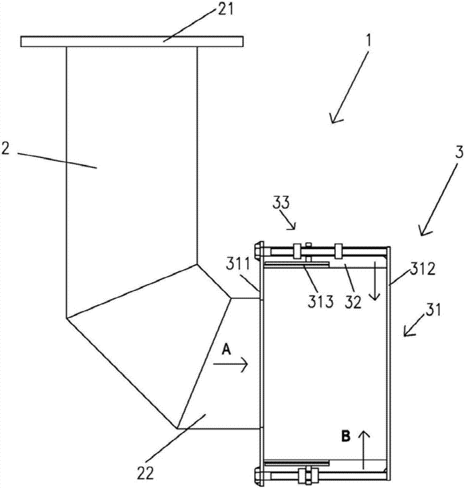
[0040] figure 2 4 shows the schematic structure of the smoke distributing device 3 according to the first embodiment of the present invention.

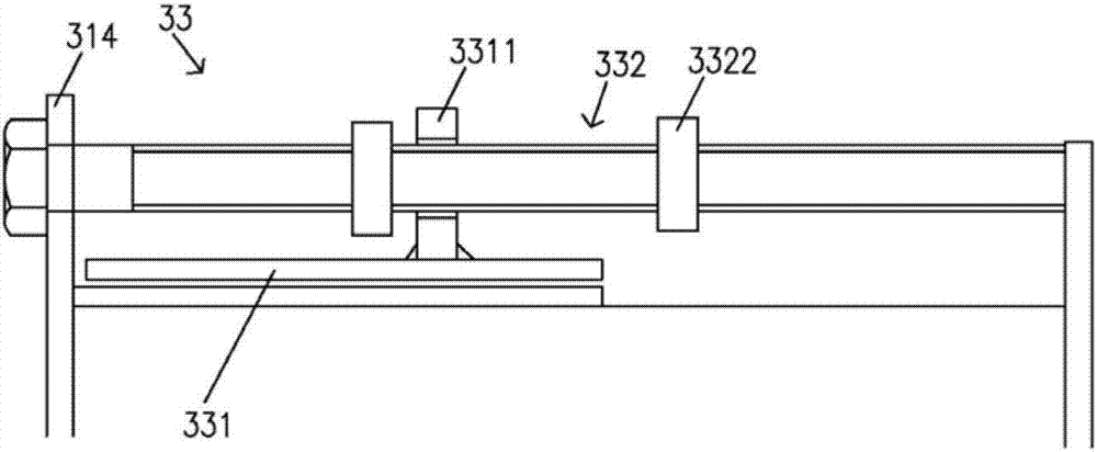
[0041] Such as figure 2 As shown, the smoke distribution device 3 includes a cylindrical body 31 , a plurality of air inlets 32 disposed on the cylindrical body 31 , and an adjusting device 33 for adjusting the intake area of ​​the air inlets 32 .

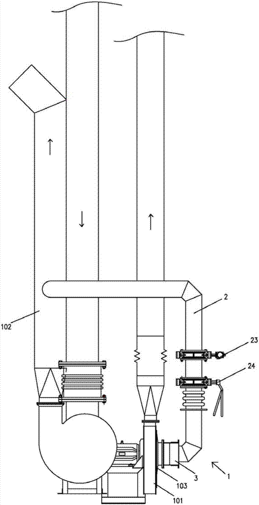
[0042] The cylindrical body 31 includes a first end 311 for connecting with the flue gas return pipe 2 , a second end 312 for connecting to the fan inlet 103 and a side wall extending between the first end 311 and the second end 312 313.

[0043] The first end 311 is provided with an opening for connecting the outlet end 22 of the flue gas return pipe 2 , so as to introduce the flue gas discharged from the outlet end 22 into the cylindrical body 31 . The outlet port 22 is preferably disposed at the center of the first end 311 , that is, the opening is disposed at the center of the fir...

no. 2 example

[0056] Figure 5 The schematic structure of the smoke distributing device 1 according to the second embodiment of the present invention is shown. The second embodiment differs from the first embodiment only in that the outlet end 22 of the flue gas return pipe 2 extends from the first end 311 of the cylindrical body 31 of the smoke distribution device 3 through the interior of the cylindrical body 31 and reaches the cylinder. The second end 312 of the shaped body 31 is formed to form a mixing zone of smoke and air at the end face of the second end 312 (ie, the plane where the end is located). Other parts of this embodiment can be the same as the first embodiment. For brevity, only this difference is described here.

[0057] In this embodiment, the outlet end 22 of the flue gas return pipe 2 passes through the cylindrical body 31 of the smoke distribution device 3 , thereby forming an annular space 34 in the cylindrical body 31 of the smoke distribution device 3 to receive th...

no. 3 example

[0060] Fig. 7(a) and Fig. 7(b) show a schematic structural diagram of a smoke distributing device according to a third embodiment of the present invention. The difference between this embodiment and the first embodiment is that the second end 312 of the smoke distribution device 3 is provided with a transition section 3120 connected to the fan inlet, so as to adapt to different spatial arrangements of various industrial furnaces. The transition section 3120 may have a taper such as a cone for direct or indirect connection with the fan inlet. The transition section 3120 may also have a straight portion connected to the tapered portion, and the straight portion may be directly or indirectly connected to the fan inlet. However, the transition section 3120 may also take other cylindrical shapes as long as it is properly connected to the fan inlet for supplying combustion air.

[0061] Figure 7(a) shows that the air inlet 32 ​​is arranged close to the second end 312 of the smoke d...


PUM


Abstract

The invention provides a smoke distributing device and a smoke distributing assembly for reducing nitride emission of a heat accumulating type burning industrial furnace and the industrial furnace. The industrial furnace comprises a burner, a draught fan for supplying combustion air and a smoke discharging pipe; the draught fan is provided with a draught fan inlet connected with the smoke distributing device; the smoke distributing device comprises a barrel-shaped body, a plurality of air inlets and an adjusting device, the barrel-shaped body has a first end used for being connected with a smoke backflow pipe, a second end connected to the draught fan inlet and a side wall between the first end and the second end, a smoke backflow pipe guides smoke in the smoke discharging pipe to flow back to the draught fan; the multiple air inlets are formed in the side wall for guiding in external air; the adjusting device is used for adjusting the air inlet areas of the multiple air inlets so as to allocate the mixing ratio of smoke and air in advance; and when the smoke backflow pipe and the smoke distributing device are connected to the industrial furnace, the backflow smoke and introduced air are mixed into combustion air by means of the negative pressure of the draught fan inlet before introduced into the draught fan inlet. By means of the smoke distributing device, the smoke distributing assembly and the industrial furnace, the nitride in discharged smoke is greatly reduced.

Description

technical field [0001] The invention relates to a smoke distribution device for a regenerative combustion industrial furnace, a smoke distribution assembly and an industrial furnace with the smoke distribution device. Background technique [0002] In order to save energy, especially for the control of multiple temperature zones, multiple burners are required, and periodic industrial furnaces with huge changes in energy supply, such as trolley heating furnaces, trolley heat treatment furnaces, and chamber furnaces in forging and foundry industries. At present, regenerative combustion technology is widely used in order to obtain the ultimate heat recovery. The temperature of the flue gas discharged through regenerative combustion is only about 100-150 °C. For periodic industrial furnaces, the energy supply in the heating stage is generally 100% of the set capacity, and after heat preservation, when the heat absorption of the workpiece and the furnace body are nearing the end, ...

Claims


Application Information

Patent Timeline
IPC IPC(8): F27D17/00F23C9/06
CPCF23C9/06F27D17/001F27D17/004F27D2017/007Y02E20/34
Inventor 顾向涛刘义宋长春高健宫立兵
Owner 重庆沃克斯博能科技有限公司
Why Eureka
Try Eureka