
Center fuel nozzle

A fuel nozzle and fuel pipe technology, which is applied to combustion chambers, combustion methods, combustion equipment, etc., can solve the problems of inability to ensure the uniformity of fuel and air mixing, increase combustion chamber emissions, easily cause backfire, etc., to prevent wakes. , the effect of reducing emissions and preventing the risk of backfire

Active Publication Date: 2019-04-19
AECC SHENYANG ENGINE RES INST
View PDF7 Cites 5 Cited by
  • Summary
  • Abstract
  • Description
  • Claims
  • Application Information

AI Technical Summary

Problems solved by technology

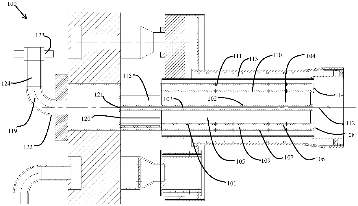
[0004] The nozzle in the center area of ​​the existing dry-type low NOx combustor supplies fuel through the fuel spray rod, which cannot ensure the uniformity of fuel and air mixing, which may cause local over-rich fuel and increase combustion chamber emissions; at the same time, the fuel spray rod is located in the premixing channel , after the air flows through the fuel spray rod, it produces a wake, which is easy to cause the risk of flashback

Method used


Image

  • Center fuel nozzle
  • Center fuel nozzle
  • Center fuel nozzle

Examples


Embodiment Construction

[0036] In order to make the purpose, technical solution and advantages of the application more clear, the technical solution in the embodiment of the application will be described in more detail below in conjunction with the drawings in the embodiment of the application. In the drawings, the same or similar reference numerals denote the same or similar elements or elements having the same or similar functions throughout. The described embodiments are some, but not all, embodiments of the application. The embodiments described below by referring to the figures are exemplary, and are intended to explain the present application, and should not be construed as limiting the present application. Based on the embodiments in this application, all other embodiments obtained by persons of ordinary skill in the art without creative efforts fall within the protection scope of this application. Embodiments of the present application will be described in detail below in conjunction with th...


PUM

PropertyMeasurementUnit
Diameteraaaaaaaaaa

Abstract

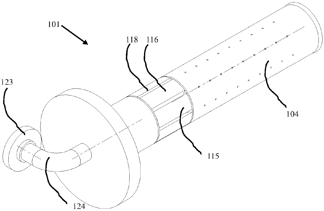
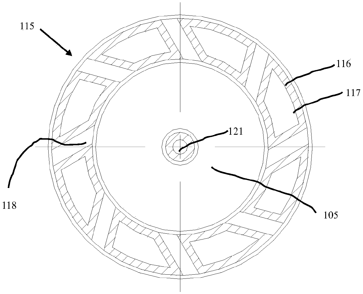
The invention belongs to the technical field of turbine engines, and particularly relates to a center fuel nozzle. The center fuel nozzle (101) is arranged in a gas turbine combustion chamber (100), and comprises an on-duty fuel pipe (102), a fuel distributing pipe (104), a rotational flow pipe (115) and an inlet segment (122). According to the center fuel nozzle, the design of a traditional fuelspraying rod is omitted, through an inner fuel hole and an outer fuel hole, multi-point fuel putting is carried out, the mixed uniform degree of fuel and air can be reinforced, the emission amount ofthe combustion chamber can be reduced, the inner fuel hole and the outer fuel hole replace the fuel spraying rod in a pre-mixed channel to prevent back traces, and tempering risks of the combustion chamber are prevented.

Description

technical field [0001] The application belongs to the technical field of turbine engines, and in particular relates to a central fuel nozzle. Background technique [0002] A gas turbine engine includes a compressor, a combustion system, and a turbine. In a combustion system, air is combusted with fuel to generate hot gases that are expanded in a turbine section to drive a load. Usually the combustion system uses a diffusion burner, in which the fuel diffuses directly into the burner, mixes with air and burns. Diffusion burners, however, operate at high peak temperatures and can form relatively high levels of pollutants such as nitrogen oxides (NOx). [0003] In the prior art, a dry low NOx combustion system is used to reduce the level of NOx produced during the combustion process. The combustion system uses lean premixed combustion, which premixes air and fuel to form a relatively uniform air-fuel mixture before directing the mixture into the combustion zone. This mixtur...

Claims


Application Information

Patent Timeline
IPC IPC(8): F23R3/38F23R3/28
CPCF23R3/286F23R3/38
Inventor 齐兵陈明禄金戈张善军
Owner AECC SHENYANG ENGINE RES INST
Learn More