Reaction Injection Molding System Based on Dicyclopentadiene

A dicyclopentadiene and injection molding technology, applied in the field of injection molding, can solve the problems of high resistance in the filling process, influence on coating, low efficiency and low product qualification rate, and achieve the effect of realizing intelligent and precise control and overcoming waste of raw materials

Active Publication Date: 2021-06-04
成都东日瑞姆机械有限公司
View PDF15 Cites 0 Cited by
  • Summary
  • Abstract
  • Description
  • Claims
  • Application Information

AI Technical Summary

Problems solved by technology

However, there is no special production equipment for DCPD injection products in the prior art, and conventional reaction injection molding equipment is used for production, but this equipment is not fully functional and cannot meet the production and use of DCPD injection molding, and a large number of defects are prone to occur during the production process: The inventors of this case found out during a lot of research that the resistance in the filling process is too large due to the air in the cavity that has not been discharged, and it is difficult to fill the cavity. In order to fill the cavity, the existing technology generally adopts an excessive injection method. This leads to a large amount of waste of raw materials and the inability to accurately control the injection process. This phenomenon is particularly prominent in the injection process of complex parts; the aforementioned defects need to be repaired by manual puttying and other methods, resulting in low efficiency and product qualification rate
In addition, during the production process of DCPD stock solution, a large number of tiny bubbles will be mixed in due to stirring, and these tiny bubbles will be evenly distributed on the surface and inside of the product as the injection progresses. The bubbles on the surface will affect the subsequent coating, and the bubbles inside will affect the product. Intensity, which is also the main reason why this technology has not been able to be widely used

Method used


Image

  • Reaction Injection Molding System Based on Dicyclopentadiene
  • Reaction Injection Molding System Based on Dicyclopentadiene
  • Reaction Injection Molding System Based on Dicyclopentadiene

Examples


Embodiment 1

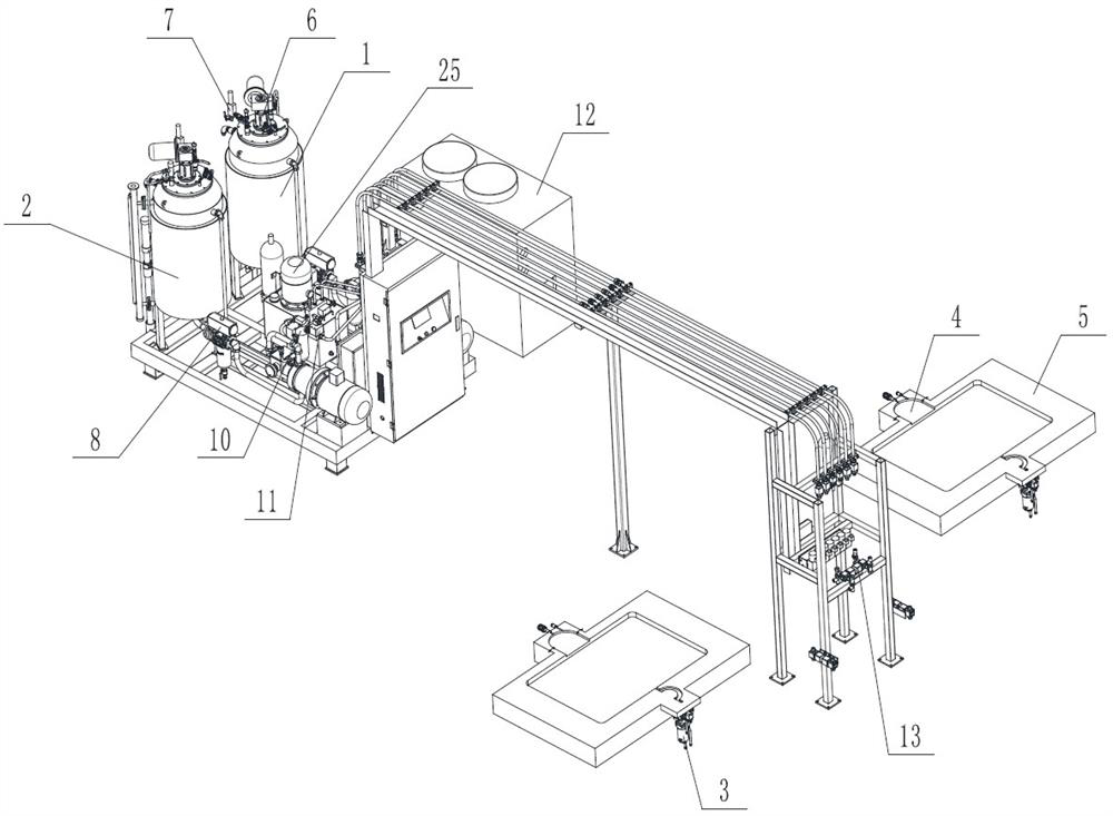
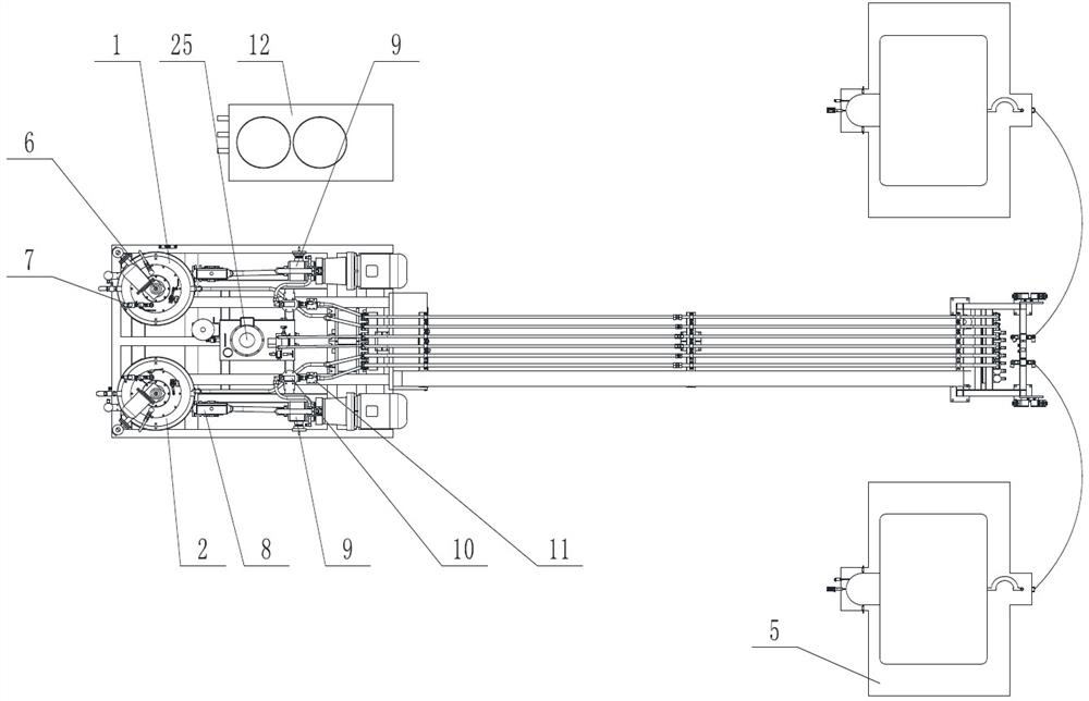
[0049] like figure 1 and figure 2 The shown reaction injection molding system based on dicyclopentadiene includes a first material tank 1 and a second material tank 2, and the first material and the second material are respectively transferred from the first material tank 1 and the second material tank through a pumping system. 2 is delivered to the mixing head 3; also includes a mold 5 for dicyclopentadiene reaction injection molding, the overflow bag 4 communicated with the inside of the mold cavity is set on the mold 5, and the mixing head 3 and the overflow bag 4 are set On opposite sides of the mold 5 , the mixing head 3 is used to pour the mixed raw materials into the mold 5 , and the overflow bag 4 is provided with a liquid level sensor 14 ; The first material tank 1 and the second material tank 2 are equipped with a stirring device 6 and a vacuum generating device 7 .

[0050] It should be noted that, for the convenience of illustration, the mold 5 in the drawings o...

Embodiment 2

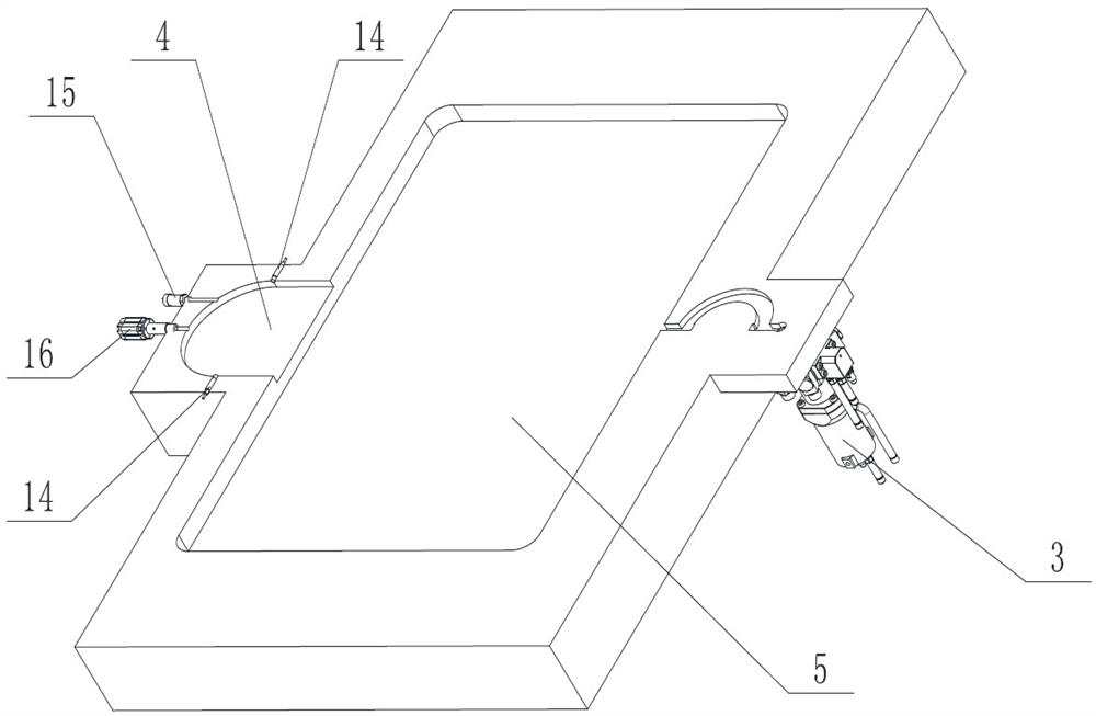
[0058] On the basis of Example 1, such as image 3 As shown, a pressure sensor 15 located in the overflow bag 4 is also included, and the pressure sensor 15 is located on the side of the liquid level sensor 14 away from the mold cavity. It also includes an exhaust valve 16 arranged on the overflow bag 4 .

[0059] In one or more preferred embodiments, the exhaust valve 16 is as Figure 7 and Figure 8 As shown, it includes a housing 161 and an exhaust pin 162 slidingly fitted in the housing 161. There are several exhaust gaps 163 between the exhaust pin 162 and the housing 161; an exhaust port is set on the housing 161 24 , the exhaust port 24 communicates with the exhaust gap 163 . Also comprise the cleaning device that is used to push exhaust pin 162 out housing 161; Said cleaning device comprises the cleaning cylinder 17 that links to each other with exhaust valve 16, the reversing valve 18 that matches with cleaning cylinder 17, and described cleaning cylinder 17 The o...

Embodiment 3

[0065] On the basis of any of the above-mentioned embodiments, a switching valve 13 is also provided between the flow meter 11 and the mixing head 3; the switching valve 13 includes a first station and a second station:

[0066] When the switching valve 13 is at the first station, the first raw material and the second raw material enter the mixing head 3;

[0067] When the switching valve 13 is at the second position, the first raw material and the second raw material flow back to the first material tank 1 and the second material tank 2 respectively.

[0068] The switching valve 13 of the present embodiment is as Figure 4 to Figure 6 As shown, it includes two valve bodies 131 respectively corresponding to the first raw material and the second raw material, and each valve body 131 is clearance fit with the valve core 132, and the valve body 131 is connected with two three-way joints 133; Based on the driving mechanism that drives the spool 132 to move, the spool 132 can conne...


PUM


Abstract

The invention discloses a reaction injection molding system based on dicyclopentadiene, which includes a first material tank and a second material tank, and the first raw material and the second material are transported from the first material tank and the second material tank to the Mixing head; also includes the mold that is used for dicyclopentadiene reaction injection molding, and the overflow bag that communicates with mold cavity inside is arranged on described mold, and described mixing head, overflow bag are arranged on the relative both sides of mould, and mixing head It is used for pouring mixed raw materials into the mould, and a liquid level sensor is set in the overflow bag or the mould; it also includes a vacuum extraction device for vacuuming the mould. The present invention is used to solve the above-mentioned problems caused by the lack of production equipment dedicated to dicyclopentadiene injection products in the prior art, realize the production and preparation of dicyclopentadiene injection products through a special system, realize intelligent control of the injection process, and improve product quality. The purpose of quality, so that the technology can be widely used.

Description

technical field [0001] The invention relates to the field of injection molding, in particular to a reaction injection molding system based on dicyclopentadiene. Background technique [0002] DCPD is a new olefin cross-linked thermosetting resin with dicyclopentadiene as the main raw material. It is a new material that can produce large or complex shaped molded parts in a very short time. DCPD products are suitable for the production of large parts, with good strength and low temperature performance, especially suitable for automotive interior parts such as shrouds, box panels of vans, bumpers and other fields. However, there is no special production equipment for DCPD injection products in the prior art, and conventional reaction injection molding equipment is used for production, but this equipment is not fully functional and cannot meet the production and use of DCPD injection molding, and a large number of defects are prone to occur during the production process: The inv...

Claims


Application Information

Patent Timeline
Patent Type & Authority Patents(China)
IPC IPC(8): B29C44/42B29C44/34B29C44/60
CPCB29C44/3403B29C44/3442B29C44/35B29C44/424B29C44/60
Inventor 鲁玉凡谭正亮鲁云飞黄鑫孙永琦邓理坤
Owner 成都东日瑞姆机械有限公司
Why Eureka
Try Eureka