Rotor of rotating electric machine and method of assembling rotor of rotating electric machine

a technology of rotating electric machines and rotors, which is applied in the direction of manufacturing stators/rotor bodies, magnetic circuit rotating parts, and shape/form/construction of magnetic circuits, etc., can solve the problems of affecting the performance of rotating electric machines, leaking magnetic flux through gaps, and difficulty in installing reinforcing members

Active Publication Date: 2008-08-19
MITSUBISHI ELECTRIC CORP
View PDF7 Cites 2 Cited by
  • Summary
  • Abstract
  • Description
  • Claims
  • Application Information

AI Technical Summary

Benefits of technology

[0008]The present invention is intended to solve the aforementioned problems of the prior art. Accordingly, it is an object of the invention to provide a structure of a rotor of a rotating electric machine, the structure including magnet-mounting members for fixing magnets in gaps between adjacent claw-shaped magnetic poles of the rotor in a reliable fashion so that the magnets will not be displaced in either a basal-end or extreme-end direction of the claw-shaped magnetic poles, wherein the structure makes it possible to easily mount the magnet-mounting members on the respective claw-shaped magnetic poles after disposing the magnets between side faces of the adjacent claw-shaped magnetic poles.
[0009]According to the invention, a rotor of a rotating electric machine includes a pole core surrounding a rotor coil for generating magnetic flux, the pole core including a first pole core body having claw-shaped magnetic poles and a second pole core body having claw-shaped magnetic poles, the claw-shaped magnetic poles of the first and second pole core bodies extending alternately from opposite directions, intermeshing one another. The rotor further includes a plurality of permanent magnets disposed against both side faces of each of the claw-shaped magnetic poles for reducing leakage of the magnetic flux from between the facing side faces of the adjacent claw-shaped magnetic poles, and a plurality of magnet-mounting members for fixedly holding the permanent magnets against both side faces of each of the claw-shaped magnetic poles. Each of the magnet-mounting members has a generally C-shaped cross section, including a flat, platelike middle portion which fits on an inclined inside surface of each of the claw-shaped magnetic poles, and a pair of magnet-retaining portions formed on both sides of the middle portion for holding two of the permanent magnets on both sides of each of the claw-shaped magnetic poles, each of the magnet-retaining portions having hooking tabs extending therefrom for preventing each of the permanent magnets from being displaced in either a basal-end or extreme-end direction of each of the magnet-mounting members. A magnet-retaining function of the hooking tabs to prevent displacement of the permanent magnets can be disabled by altering an original state of a pair of basal-end hooking tabs of each magnet-mounting member.
[0010]In this rotor of the rotating electric machine, the magnet-retaining function of the hooking tabs to prevent displacement of the permanent magnets can be disabled by altering the state of a pair of basal-end hooking tabs of each magnet-mounting member as stated above. This feature of the invention permits disabling the magnet-retaining function of the hooking tabs to prevent displacement of the permanent magnets disposed against both side faces of each of the claw-shaped magnetic poles before fitting the magnet-mounting members on the claw-shaped magnetic poles, making it possible to push the magnet-mounting members onto the respective claw-shaped magnetic poles while preventing the basal-end hooking tabs from interfering with the permanent magnets. As the magnet-mounting members can be easily mounted onto the individual claw-shaped magnetic poles already fitted with the permanent magnets on both sides in this way, the aforementioned structure of the invention serves to provide enhanced ease of assembling the rotor, yet preventing the permanent magnets from being displaced in a reliable fashion after the magnet-mounting members have been mounted on the respective claw-shaped magnetic poles.
[0011]According to the invention, a method of assembling a rotor of a rotating electric machine is for assembling a rotor including a pole core surrounding a rotor coil for generating magnetic flux, the pole core including a first pole core body having claw-shaped magnetic poles and a second pole core body having claw-shaped magnetic poles. This method of assembling a rotor includes the steps of disposing a plurality of permanent magnets for reducing leakage of the magnetic flux from between facing side faces of the adjacent claw-shaped magnetic poles against both side faces of each of the claw-shaped magnetic poles, fitting magnet-mounting members on the individual claw-shaped magnetic poles, each of the magnet-mounting members having a generally C-shaped cross section and including a flat, platelike middle portion which fits on an inclined inside surface of each of the claw-shaped magnetic poles, and a pair of magnet-retaining portions formed on both sides of the middle portion for holding two of the permanent magnets on both sides of each of the claw-shaped magnetic poles, each of the magnet-retaining portions having hooking tabs extending therefrom for preventing each of the permanent magnets from being displaced in either a basal-end or extreme-end directions of each of the magnet-mounting members, and forming the pole core by combining the first and second pole core bodies whose claw-shaped magnetic poles have been fitted with the magnet-mounting members with the permanent magnets already disposed against both side faces of each of the claw-shaped magnetic poles in such a manner that the claw-shaped magnetic poles of the first and second pole core bodies extend alternately from opposite directions, intermeshing one another. A magnet-retaining function of the hooking tabs to prevent displacement of the permanent magnets is disabled by altering an original state of a pair of basal-end hooking tabs of each magnet-mounting member when the magnet-mounting members are fitted on the claw-shaped magnetic poles and the magnet-retaining function is re-enabled when the magnet-mounting members have been fitted.
[0012]In the aforementioned method of assembling a rotor of a rotating electric machine, the permanent magnets are first disposed against both side faces of each of the claw-shaped magnetic poles and, then, the magnet-mounting members are fitted on the claw-shaped magnetic poles with the magnet-retaining function of the magnet-mounting members disabled by altering the state of the pair of basal-end hooking tabs of each magnet-mounting member. The magnet-retaining function is re-enabled by returning the basal-end hooking tabs to the original state when the magnet-mounting members have been fitted on the individual claw-shaped magnetic poles. This feature of the invention makes it possible to push the magnet-mounting members onto the respective claw-shaped magnetic poles while preventing the basal-end hooking tabs from interfering with the permanent magnets. As the magnet-mounting members can be easily mounted onto the individual claw-shaped magnetic poles already fitted with the permanent magnets on both sides in this way, the aforementioned assembling method of the invention serves to provide enhanced ease of assembling the rotor, yet preventing the permanent magnets from being displaced in a reliable fashion after the magnet-mounting members have been mounted on the respective claw-shaped magnetic poles.

Problems solved by technology

This conventional arrangement has a problem that, if the reinforcing members having the aforementioned magnet-retaining structure are to be installed after the permanent magnets have been fitted on both sides of each claw-shaped magnetic pole, it is difficult to install the reinforcing members, because the magnet-retaining structure of each reinforcing member interferes with the permanent magnets.
Another problem of the conventional arrangement is that, if the reinforcing members are to be installed after the permanent magnets have been affixed to each reinforcing member, gaps are likely to be created between the permanent magnets and the side faces of each claw-shaped magnetic pole, thereby causing leakage of magnetic flux through the gaps and eventual performance degradation of the rotating electric machine.

Method used


Image

  • Rotor of rotating electric machine and method of assembling rotor of rotating electric machine
  • Rotor of rotating electric machine and method of assembling rotor of rotating electric machine
  • Rotor of rotating electric machine and method of assembling rotor of rotating electric machine

Examples


first embodiment

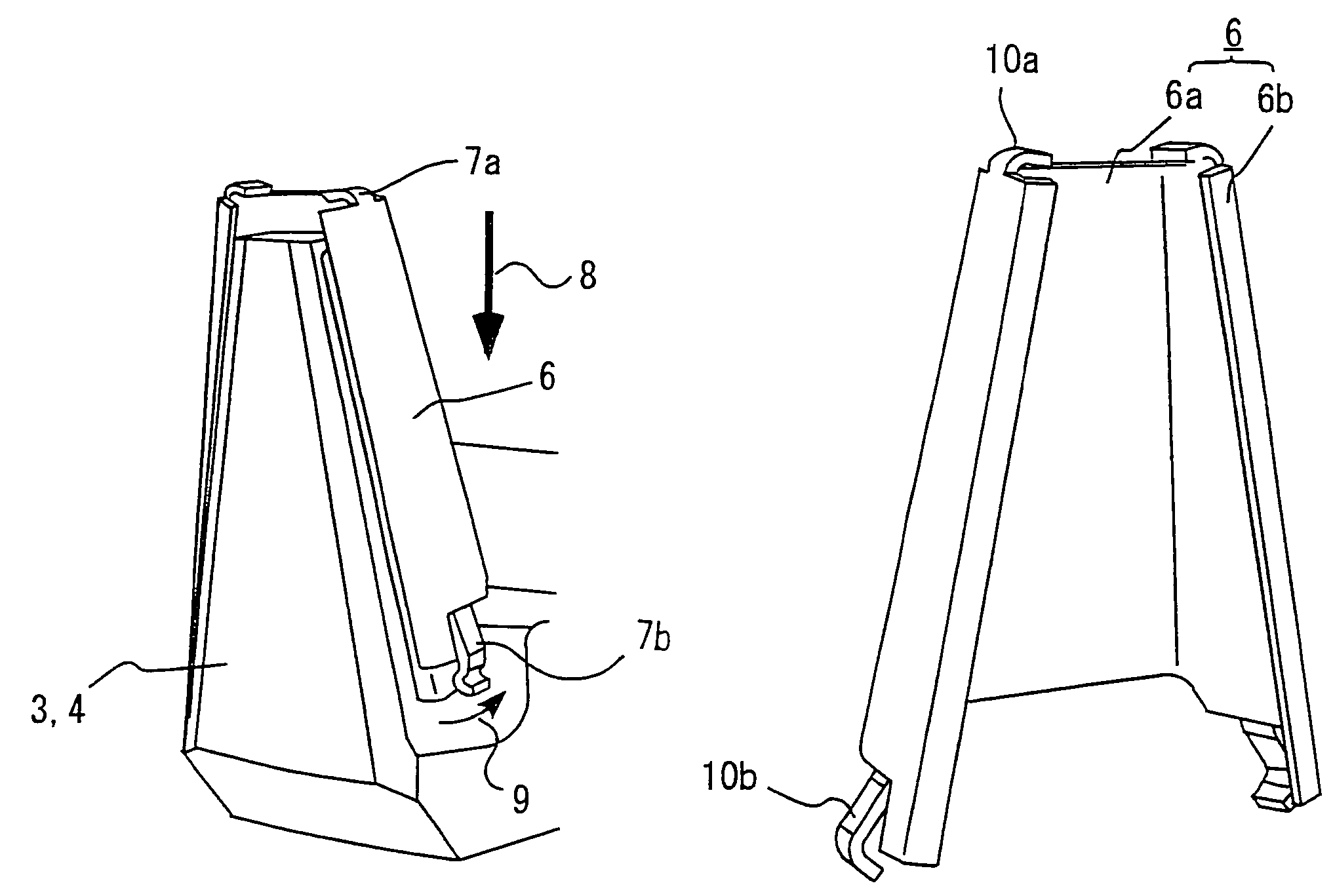
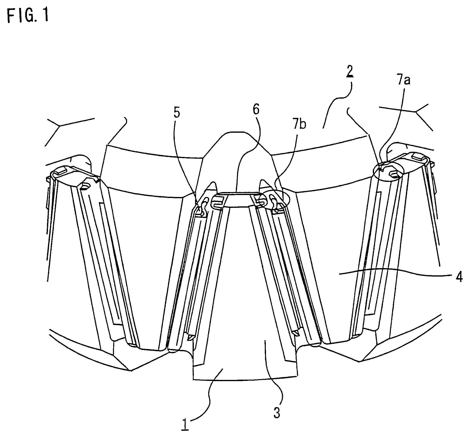
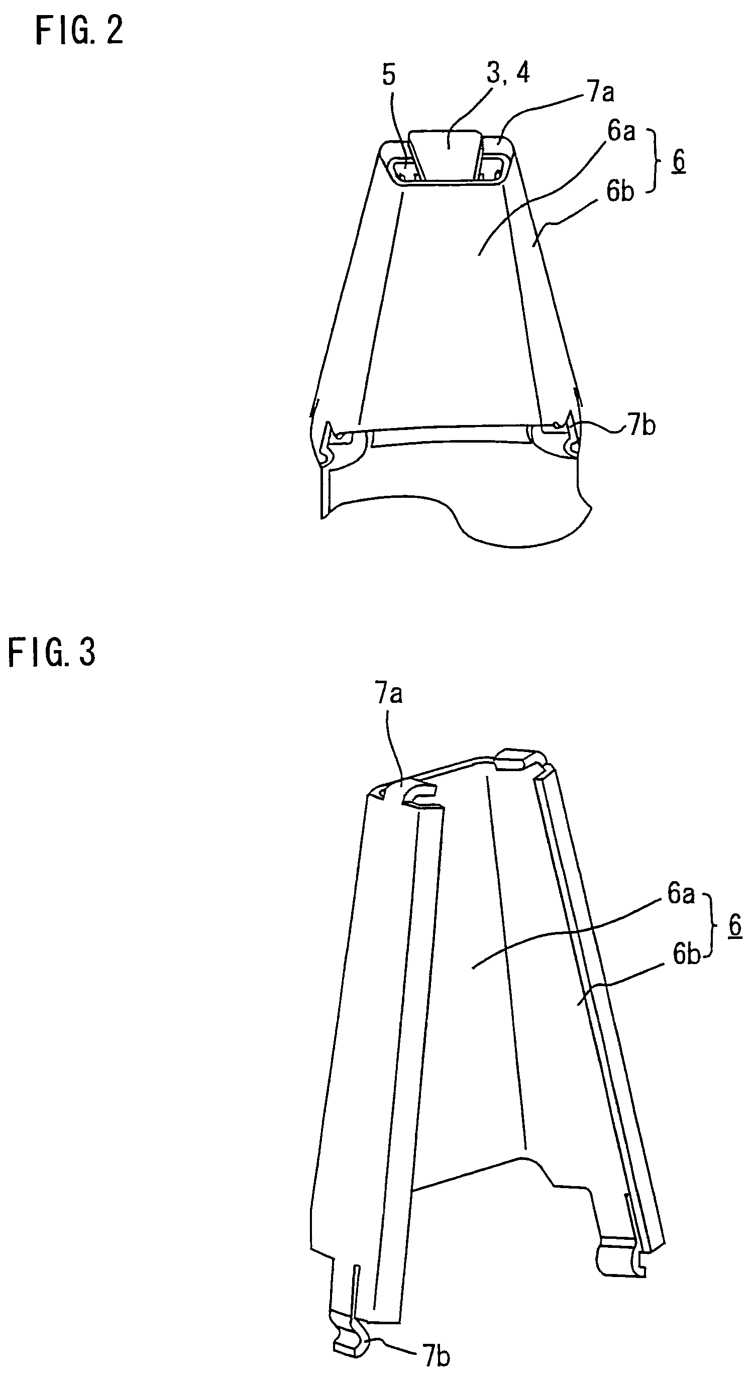
[0022]FIG. 1 is a perspective view showing a principal portion of a rotor of a rotating electric machine according to a first embodiment of the invention. Referring to FIG. 1, the rotor includes a pole core made up of a first pole core body 1 and a second pole core body 2, the pole core surrounding a rotor coil (not shown) for producing magnetic flux. The first and second pole core bodies 1, 2 respectively have claw-shaped magnetic poles 3 and 4 which extend alternately from opposite directions intermeshing one another, each of the claw-shaped magnetic poles 3, 4 narrowing from a basal end toward an extreme end. The rotor is provided with permanent magnets 5 which are disposed between facing side faces of the claw-shaped magnetic poles 3, 4 to reduce leakage of the magnetic flux through gaps between the side faces of the adjacent claw-shaped magnetic poles 3, 4. The rotor is further provided with magnet-mounting members 6 for fixedly holding the permanent magnets 5 against both side...

second embodiment

[0029]FIG. 5 is a perspective view showing the construction of a magnet-mounting member 6 according to a second embodiment of the invention. Like the magnet-mounting member 6 of the first embodiment, the magnet-mounting member 6 of this embodiment has a flat, platelike middle portion 6a which fits on an inclined inside surface of each claw-shaped magnetic pole 3 (4) and a pair of magnet-retaining portions 6b formed on both sides of the middle portion 6a for holding permanent magnets 5 against side faces of the claw-shaped magnetic pole 3 (4), the middle portion 6a and the magnet-retaining portions 6b together forming a generally C-shaped cross section as illustrated. Each of the magnet-retaining portions 6b on both sides of the magnet-mounting member 6 has an extreme-end hooking tab 10a at an extreme end and a basal-end hooking tab 10b at a basal end for retaining the permanent magnet 5 in position so that the permanent magnet 5 would not be displaced in either a basal-end or extrem...


PUM

PropertyMeasurementUnit
magnetic fluxaaaaaaaaaa
magneticaaaaaaaaaa
magnetic polesaaaaaaaaaa

Abstract

A magnet-mounting member for holding permanent magnets against side faces of each claw-shaped magnetic pole has pairs of extreme-end and basal-end hooking tabs for preventing displacement of the permanent magnets in either a basal-end or extreme-end direction. The magnet-mounting member is configured such that a function of the basal-end hooking tabs to prevent displacement of the permanent magnets can be disabled by deforming the basal-end hooking tabs. When the magnet-mounting member is forced onto the claw-shaped magnetic pole, the basal-end hooking tabs go into contact with the permanent magnets and deform outward, whereby the magnet-retaining function of the basal-end hooking tabs is disabled. When the magnet-mounting member has been fully pushed onto the claw-shaped magnetic pole, the basal-end hooking tabs resume an original shape to prevent the permanent magnets from being displaced in either direction.

Description

BACKGROUND OF THE INVENTION[0001]1. Field of the Invention[0002]The present invention relates generally to a structure of a rotor of an alternating current (AC) generator or motor, and more particularly, to a structure for mounting permanent magnets in the rotor to prevent leakage of magnetic flux from between facing side faces of adjacent claw-shaped magnetic poles.[0003]2. Description of the Background Art[0004]There exist conventionally known techniques for increasing output of a rotating electric machine whose rotor includes a pair of intermeshed pole core bodies having claw-shaped magnetic poles. One of such techniques is to fit permanent magnets in gaps between one claw-shaped magnetic pole and the next which are arranged along a circumferential direction of the rotor in order to reduce leakage of magnetic flux through the gaps between the adjacent claw-shaped magnetic poles for increasing output of a rotating electric machine.[0005]Japanese Patent Application Publication No. ...

Claims


Application Information

Patent Timeline
Patent Type & Authority Patents(United States)
IPC IPC(8): H02K1/22
CPCH02K21/044Y10T29/49012Y10T29/49009
Inventor MAEDA, NAOHIDEFUJITA, MASAHIKOKUDOH, SHINYA
Owner MITSUBISHI ELECTRIC CORP
Why Eureka
Try Eureka