Eureka AIR delivers breakthrough ideas for toughest innovation challenges, trusted by R&D personnel around the world.

Helical antenna system

a technology of helical antennas and antennas, applied in the direction of antennas, antenna details, electrical equipment, etc., can solve the problems of reducing compromising the performance of the antenna, and reducing the efficiency of the antenna, so as to improve the other performance characteristics, reduce the physical dimensions of the antenna, and increase the directivity of the antenna

Active Publication Date: 2008-08-19
LOCKHEED MARTIN CORP
View PDF7 Cites 6 Cited by
  • Summary
  • Abstract
  • Description
  • Claims
  • Application Information

AI Technical Summary

Benefits of technology

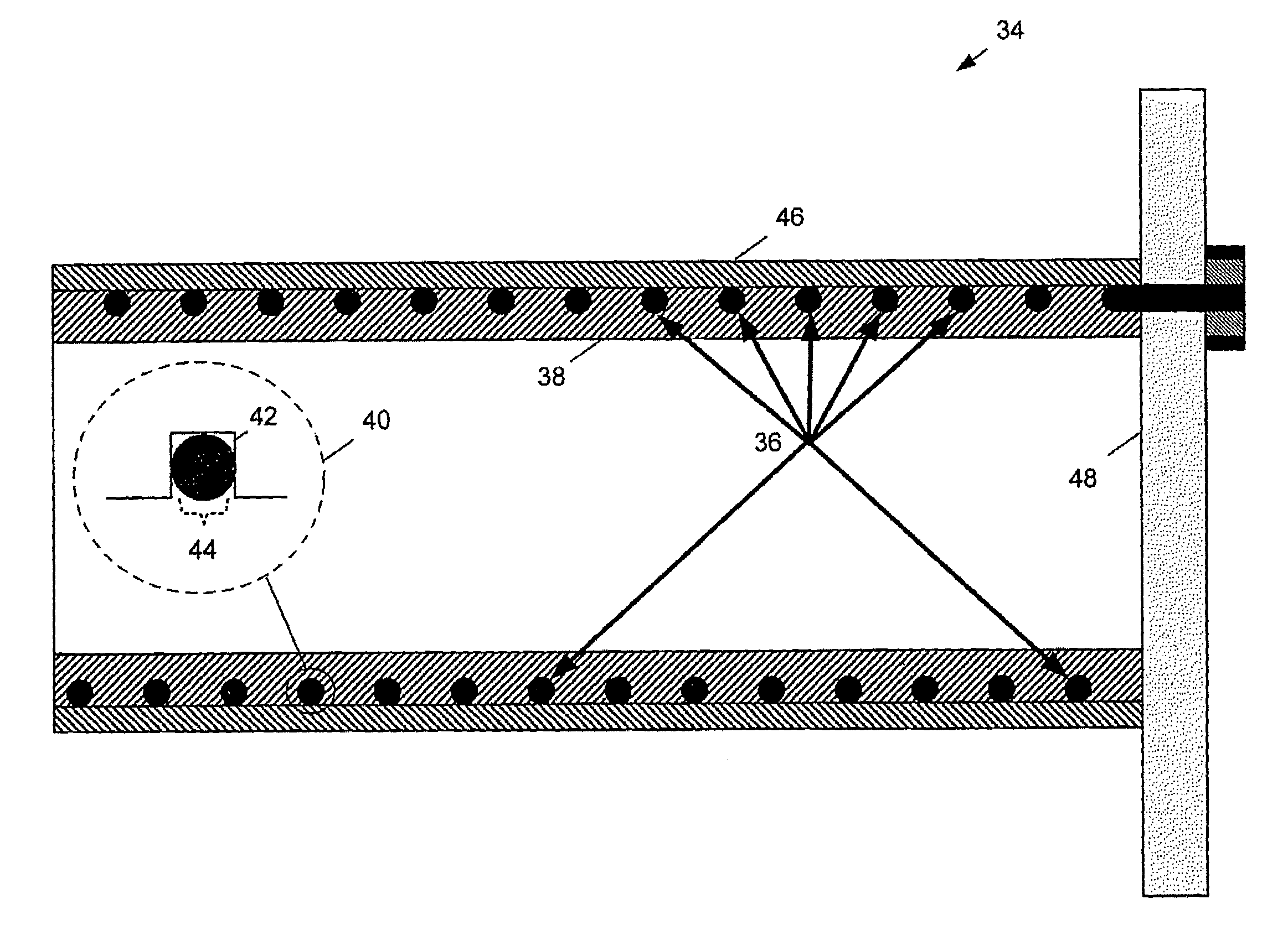
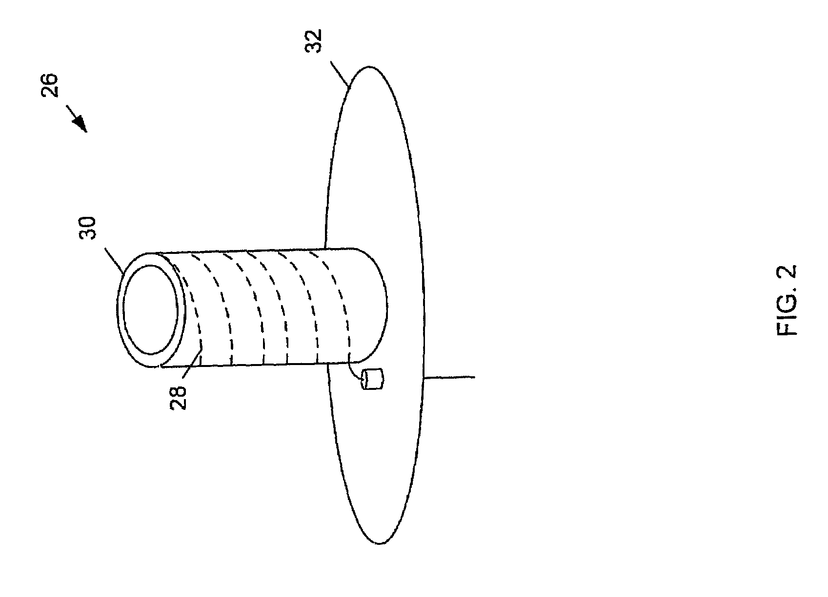
[0004]The subject matter disclosed herein solves these problems by providing a helical antenna that is embedded in a dielectric cylinder. Along with providing structural support, by embedding the helical antenna in the dielectric material, the physical dimensions of the antenna may be reduced without substantially degrading antenna performance. In particular, the helical antenna may be scaled as a function of the dielectric constant of the dielectric material. Thus, a reduced size helical antenna may provide the similar directivity as a larger helical antenna that is exposed to free space. Going one step further, the embedded helical antenna may then be extended to the pre-scaled antenna length to increase antenna directivity and improve other performance characteristics.

Problems solved by technology

In general, technological progress has produced significant advances in the miniaturization of electronic components and circuitry, however, this progress has not been mirrored by corresponding advancements in antenna miniaturization.
Theoretical work over the years, as well empirical results, indicate that reducing antenna size may cause compromises to be made in antenna performance, most notably efficiency and bandwidth.

Method used


Image

  • Helical antenna system
  • Helical antenna system
  • Helical antenna system

Examples


Embodiment Construction

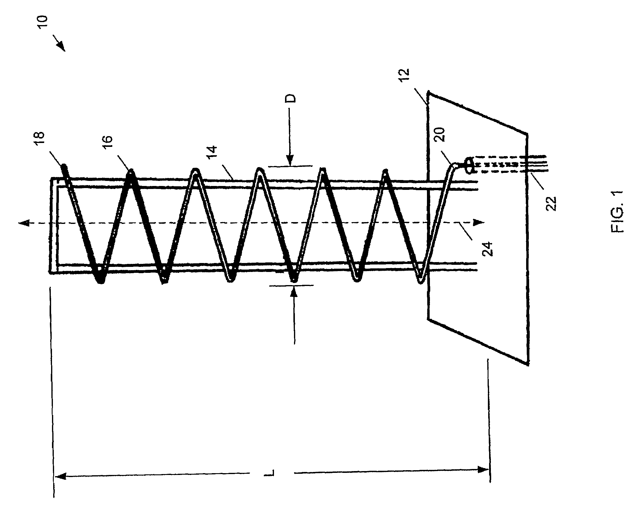
[0023]Referring to FIG. 1, a conventional helical antenna 10 includes a ground plane 12 upon which a support structure 14 is attached (e.g., bolted, welded, etc.). A conductor 16 is wrapped around support structure 14 in a spiral manner to produce a helical antenna element that may radiate or receive electromagnetic signals. Typically one end 18 of conductor 16 is terminated at the upper portion of support structure 14 and an opposing end 20 of conductor 16 is connected to a signal feed 22 that transfers electromagnetic signals to and / or from the antenna for reception or transmission. When used for transmission, helical antennas such as helical antenna 10 radiate a substantial portion of electromagnetic energy along an axis 24 of the helix that is created by conductor 16. This type of radiation pattern is typically referred to as an “end-fire” radiation pattern. Alternatively, if used for receiving electromagnetic signals, helical antenna 10 provides maximum reception along axis 24....


PUM


Abstract

An antenna system includes a helical antenna that includes one or more helically shaped conductors. Each conductor is substantially embedded in a dielectric structure.

Description

STATEMENT AS TO RIGHTS TO INVENTIONS MADE UNDER FEDERALLY SPONSORED RESEARCH OR DEVELOPMENT[0001]Not Applicable.TECHNICAL FIELD[0002]This disclosure relates to a helical antenna system and, more particularly, to embedding a helical antenna in a dielectric material to reduce antenna size without degrading performance.BACKGROUND[0003]In many aspects of wireless communications, a desire exists to minimize antenna size. In general, technological progress has produced significant advances in the miniaturization of electronic components and circuitry, however, this progress has not been mirrored by corresponding advancements in antenna miniaturization. Theoretical work over the years, as well empirical results, indicate that reducing antenna size may cause compromises to be made in antenna performance, most notably efficiency and bandwidth. Additionally, antenna directivity, cross-polarization isolation, and other antenna performance characteristics may be sacrificed to reduce antenna siz...

Claims


Application Information

Patent Timeline
Patent Type & Authority Patents(United States)
IPC IPC(8): H01Q1/36
CPCH01Q1/362
Inventor LIER, ERIKFIEDZIUSZKO, SLAWOMIR J.TIZIANO, FRANCIS D.
Owner LOCKHEED MARTIN CORP
Why Eureka
Eureka Blog
Learn More