Antenna device

a technology of antenna device and antenna, which is applied in the direction of antenna, antenna details, electrical equipment, etc., can solve the problems of long communication distance between the antenna device and the antenna, and the problem of how to dispose of the antenna becomes a problem, so as to enhance the directivity of the antenna, increase the magnetic flux, and prolong the communication range of the antenna

Inactive Publication Date: 2016-08-04
TDK CORPARATION
View PDF8 Cites 5 Cited by
  • Summary
  • Abstract
  • Description
  • Claims
  • Application Information

AI Technical Summary

Benefits of technology

[0017]In this invention, it is desired that the antenna device further comprises a second metal layer having a second slit, wherein the second metal layer is provided opposite to the first metal layer as viewed from the antenna coil, and the inner diameter area of the antenna coil overlaps with the second slit in planar view. The magnetic flux intersecting with the antenna coil greatly extends around not only the first metal layer, but also the second, metal layer at the back, and then extends back to the inner diameter area of the antenna coil through the second slit. The loop size of the magnetic flux can therefore increase. This enhances the directivity of the antenna, ultimately further lengthening the communication range of the antenna.
[0018]In this invention, it is desired that a lower surface of the first magnetic layer is in contact with the second metal layer. If so configured, the first magnetic layer can be thick and arranged in the space between the first metal layer and the second meal layer. The first magnetic layer can therefore sufficiently suppress the generation of a diamagnetic field and the loss of eddy current.
[0019]In this invention, it is desired that the first metal layer has a first metal plate, a second metal plate located adjacent to the first metal plate, across the first slit, and a connecting portion bridging the first slit at one end thereof and connecting the first metal plate and the second metal plate, making them integral with each other. Since the connecting portion connects the first metal surface and the second metal surface in this configuration, the first and second metal surfaces can be treated as a single metal member. Hence, a cover having such metal surfaces can be easily manufactured. Further, the first metal surface and the second metal surface need not foe aligned with each other, and the width of the slit SL will never change.
[0020]In this invention, the first metal layer is preferably a housing of the mobile electronic apparatus that incorporates the antenna coil. If the housing of the mobile electronic apparatus is made of metal, not resin, and therefore functions as s metal shield, a part of the housing is used as an accelerator for the antenna coil. This helps to enhance the emission characteristic of the antenna, and ultimately to increase the communication range of the antenna coil.
[0021]In this invention, the first magnetic layer is preferably a magnetic sheet containing fiat metal grains. If the first magnetic layer contains fiat metal grains, the magnetic field emanating from the antenna coil can be orientated in the horizontal direction that intersects with the coil axis. Since polymer insulates the fiat metal particles from one another, the first magnetic layer can prevent the generation of an eddy current. The antenna device can therefore achieve both high magnetic permeability and low magnetic loss in the high RFID frequency band.
[0022]In the antenna device according to the present invention, the metal layer provided in the mobile electronic apparatus is used as accelerator to increase the communication range of the antenna coil. Therefore, the acceleration function can be enhanced.

Problems solved by technology

However, in general, the metal shield blocks radio waves.
If the metal shield is provided across a wide range, how to dispose the antenna becomes a problem.
As a result, a magnetic field is generated from the conductor layer, and the conductor layer makes a large loop of the magnetic flux, resulting in a longer communication distance between the antenna device and an antenna that the antenna device is communicating with.

Method used


Image

  • Antenna device
  • Antenna device
  • Antenna device

Examples


first embodiment

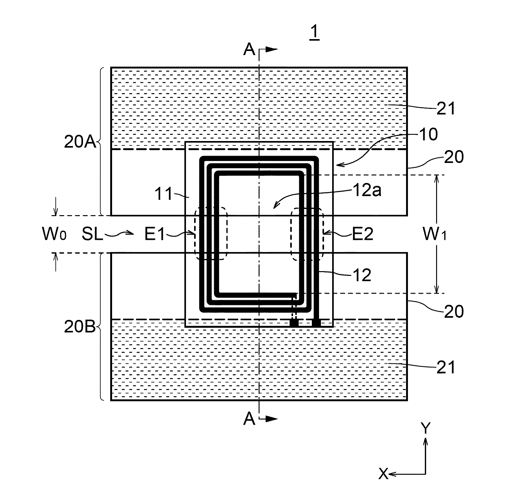
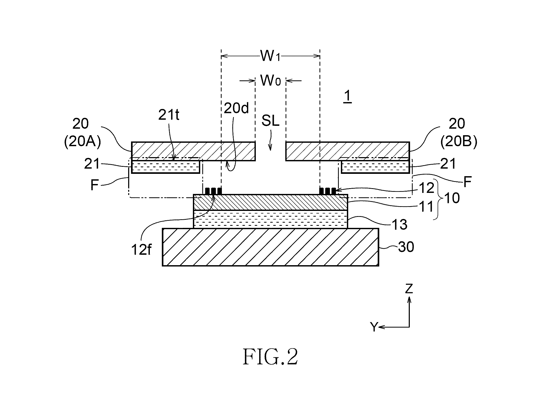
[0034]FIG. 1 is a plan view showing a configuration of an antenna device according to the present invention. FIG. 2 is a schematic cross-sectional view of the antenna device, taken along line A-A shown in FIG. 1.

[0035]As shown in FIGS. 1 and 2, the antenna device 1 comprises an antenna element 10 composed of a planer loop antenna, a first metal layer 20 covering the antenna element 10, and a first magnetic layer 21 formed on a back surface of the first metal layer 20.

[0036]The antenna element 10 comprises a substrate 11 and an antenna coil 12 formed on an upper surface of the substrate 11. The substrate 11 is a flexible substrate made of, for example, PET resin, its planer size is, for example, 40×50 mm, and its thickness is, for example, 30 μm. The substrate 11 is arranged parallel to the first metal layer 20.

[0037]The antenna coil 12 is composed of a spiral pattern which is substantially rectangular, and has a coil axis which is perpendicular to the main surface of the first metal...

second embodiment

[0050]FIG. 5 is a schematic cross-sectional view showing a configuration of an antenna device according to the present invention.

[0051]As shown in FIG. 5, the antenna device 2 according to this embodiment is characterized in that the first magnetic layer 21 is thicker than that in the first embodiment. The lower surface 21a of the first magnetic layer 21 is therefore lies below the upper surface of the substrate 11 (i.e., the surface on which the antenna coil 12 is formed). In this embodiment, the lower surface 21b of the first magnetic layer 21 is flush with the lower surface of the second magnetic layer 13. In any other respects, this embodiment is identical to the first embodiment in terms of configuration.

[0052]Preferably, the space in which the antenna element 10 interposed between a pair of first layers (i.e., left and right magnetic layers 21) should have a width almost equal to that of the width the substrate 11 has in Y direction. If the antenna device is so configured, the...

third embodiment

[0054]FIG. 6 is a schematic cross-sectional view showing a configuration of an antenna device according to the present invention.

[0055]As shown in FIG. 6, the antenna device 3 according to this embodiment is characterized in that a first magnetic layer 21 of the type used in the first embodiment extends downwards and is integrated with the second magnetic layer 13. That is, the antenna device 3 has a magnetic layer 22 formed by integrating the first magnetic layer 21 and second magnetic layer 13 used in the first embodiment. In any other respects, the third embodiment is identical to the first embodiment in terms of configuration.

[0056]According to this embodiment, the numerous magnetic fluxes generated from the current flowing in the antenna coil 12 can be guided not to foe applied to the first metal layer 20. Hence, a loop of magnetic fluxes can be formed more reliably than in the first embodiment, and the communication range of the antenna device can be reliably lengthened. Furth...


PUM


Abstract

Disclosed herein is an antenna device includes a first metal layer having a first slit, an antenna coil having an inner diameter area overlapping with the first slit in planar view and a coil axis perpendicular to the first metal layer, and a first magnetic layer provided on a back surface of the first metal layer, which faces the antenna coil, and provided outside of the antenna coil in planar view. An upper surface of the first magnetic layer facing the back surface of the first metal layer is positioned closer than a far end surface of the antenna coil to the back surface of the first metal layer along the coil axis, as viewed from the back surface of the first metal layer, or is positioned in the same plane as the far end of the antenna coil.

Description

BACKGROUND OF THE INVENTION[0001]1. Field of the Invention[0002]The present invention relates to an antenna device, and particularly to an antenna device that is suitable for NFC (Near Field Communication) system. The present invention also relates to a portable electronic device in which such an antenna device is used.[0003]2. Description of Related Art[0004]In recent years, a RFID (Radio Frequency Identification) system is incorporated in portable electronic devices such as smartphones. As a communication means for the system, an antenna is incorporated in portable electronic devices to perform near field communication with a reader / writer or the like.[0005]Meanwhile, a metal shield is provided in the portable electronic device in order to protect an internal circuit from external noise and prevent unnecessary radiation of noise generated inside the device. In particular, in order to make the body thinner, lighter, and more resistant to shock such as when the body is dropped, and ...

Claims


Application Information

Patent Timeline
Patent Type & Authority Applications(United States)
IPC IPC(8): H01Q7/06H01Q1/24
CPCH01Q1/241H01Q7/06H01Q1/2225
Inventor KOMACHI, TOSHIFUMIASOU, HIROHUMITOMONARI, TOSHIO
Owner TDK CORPARATION
Why Eureka
Try Eureka