High Gain Antenna and Wireless Device Using the Same

Active Publication Date: 2013-07-11
MEDIATEK INC
View PDF1 Cites 2 Cited by
  • Summary
  • Abstract
  • Description
  • Claims
  • Application Information

AI Technical Summary

Benefits of technology

[0008]It is therefore an objective of the present invention to provide a high gain antenna utilizing a parallel reflection metal sheet

Problems solved by technology

However, an antenna gain of 4-5 dBi derived by utilizing the parallel metal reflection sheet is not enough, and thus the pri

Method used


Image

  • High Gain Antenna and Wireless Device Using the Same
  • High Gain Antenna and Wireless Device Using the Same
  • High Gain Antenna and Wireless Device Using the Same

Examples


Embodiment Construction

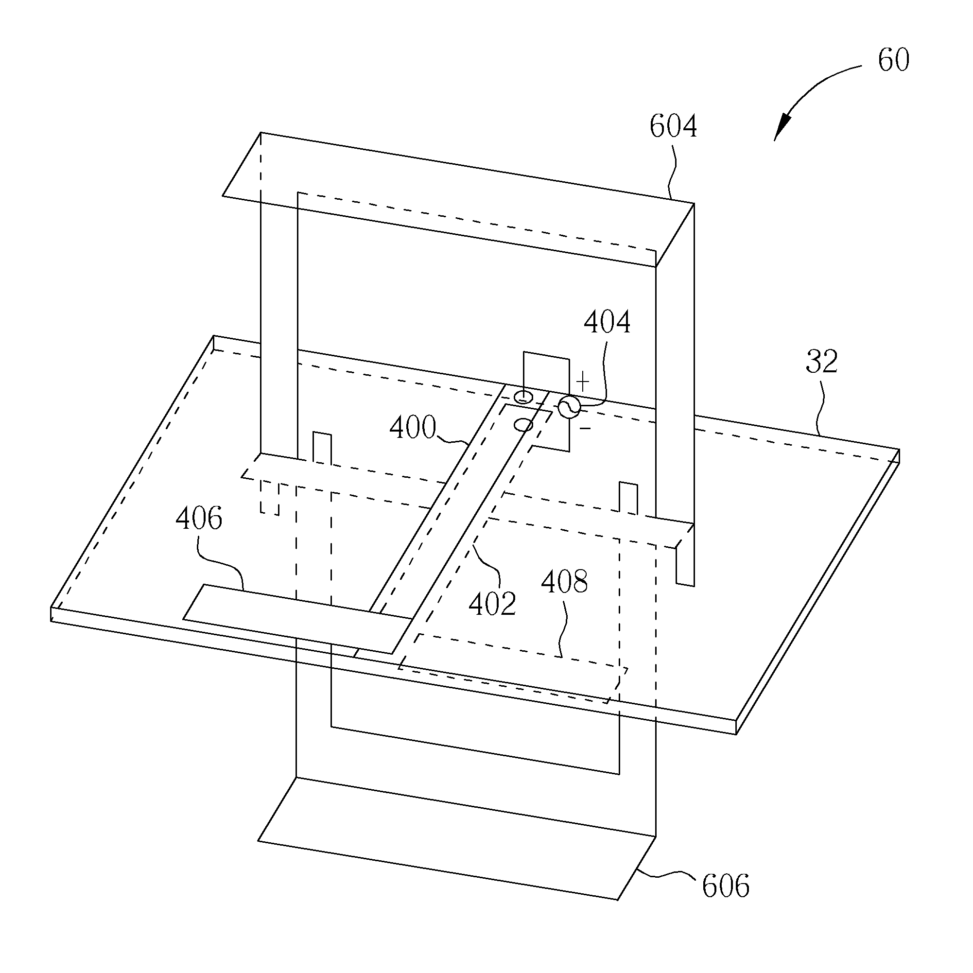
[0022]Please refer to FIG. 3, which is a schematic diagram of a high gain antenna 30 and a corresponding radiation pattern RP3 according to an embodiment of the present invention. The high gain antenna 30 is formed on a substrate, e.g. a Printed Circuit Board (PCB) 32, and includes a dipole antenna 300, a parallel reflection metal sheet 302, and vertical reflection metal sheets 304, 306. The dipole antenna 300 is formed on the PCB 32. The parallel reflection metal sheet 302 is formed on the PCB 32, and in parallel with and behind the dipole antenna 300 (−y direction). The vertical reflection metal sheet 304 is vertically disposed on a front side of the PCB 32 and behind the dipole antenna 300, and the vertical reflection metal sheet 306 is vertically disposed on a back side of the PCB 32 and behind the dipole antenna 300.

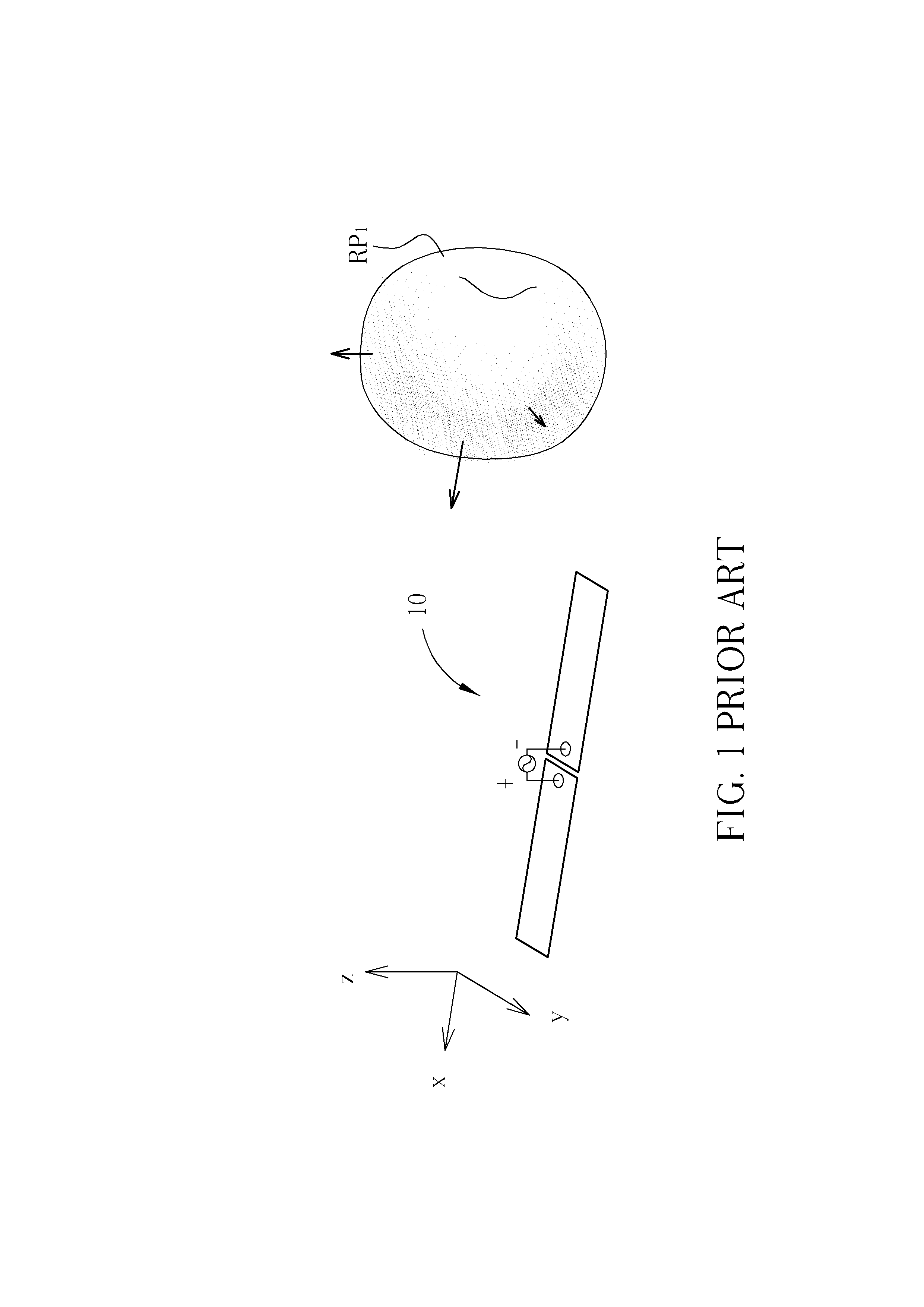
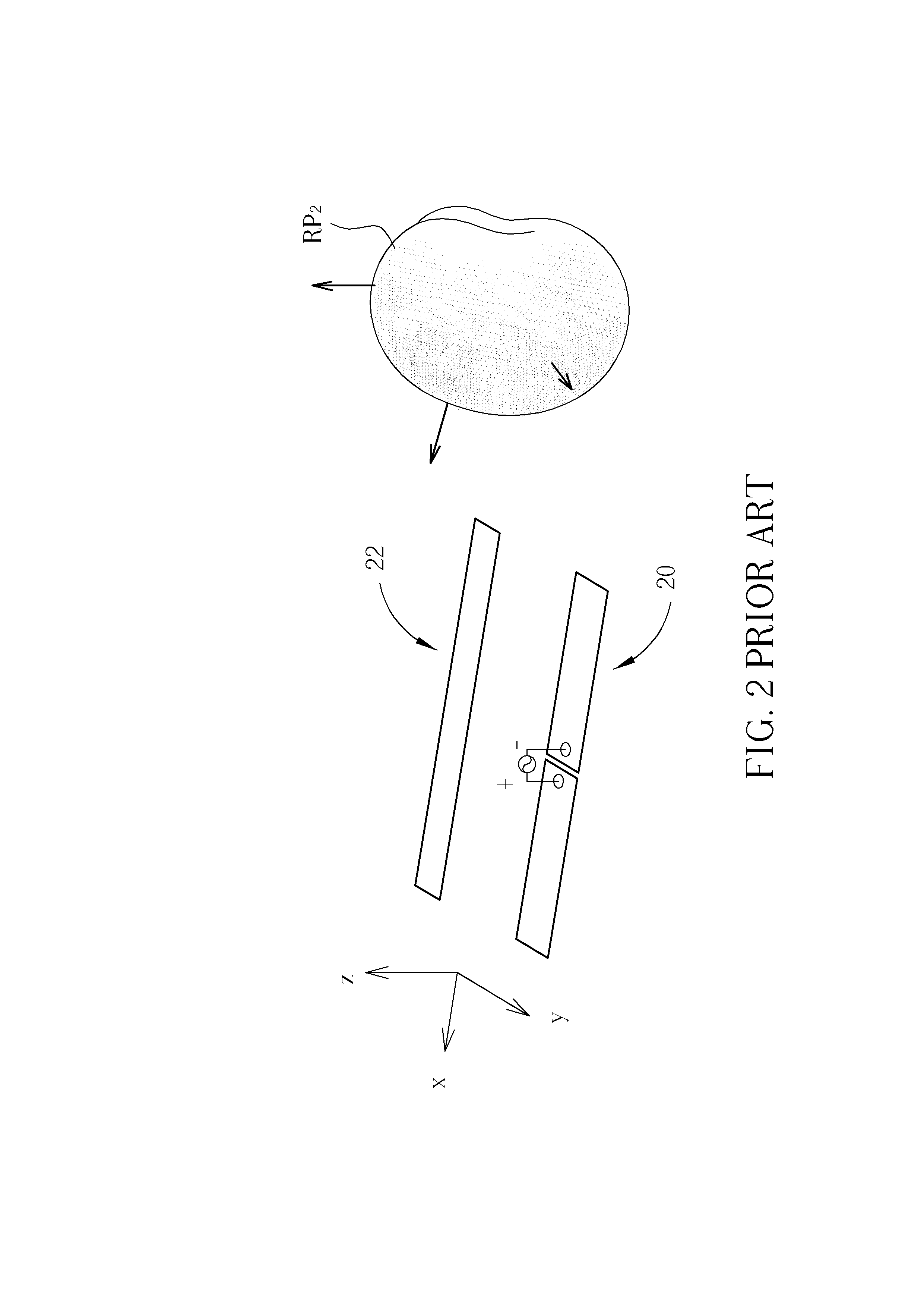
[0023]In other words, a difference between the high gain antenna 30 and the conventional dipole antenna 20 with the parallel metal reflection sheet 22 is that the h...


PUM


Abstract

The present invention discloses a high gain antenna. The high gain antenna includes a first dipole antenna, formed on a substrate; a parallel reflection metal sheet, formed on the substrate and in parallel with the first dipole antenna; a first vertical reflection metal sheet, vertically disposed on a front side of the substrate and behind the first dipole antenna; and a second vertical reflection metal sheet, vertically disposed on a back side of the substrate and behind the first dipole antenna.

Description

BACKGROUND[0001]1. Field of the Invention[0002]The present invention relates to a high gain antenna and wireless device using the same, and more particularly, to a high gain antenna and wireless device using the same utilizing a parallel reflection metal sheet plus vertical reflection metal sheets to form a three dimensional reflector, to increase antenna directivity and enhance antenna gain.[0003]2. Description of the Prior Art[0004]Antenna design is crucial to a portable device with wireless communication function, such as wireless local area network (WLAN) or other mobile communication systems. Take WLAN as an example, the antenna for an access point (AP) is usually an Omni-antenna to service stations (STA) within a certain space. Therefore, a high gain antenna at the STA helps to receive the signal from AP. Moreover, in the case when an AP uses a smart antenna, a high gain antenna will also help to improve the efficiency.[0005]Please refer to FIG. 1, which is a schematic diagram...

Claims


Application Information

Patent Timeline
IPC IPC(8): H01Q19/10H04B1/38H01Q9/16
CPCH01Q9/285H01Q19/10H01Q9/16H01Q19/28
Inventor KUO, CHENG-HAOHUANG, HSIAO-TINGLO, SHAO-CHIN
Owner MEDIATEK INC
Why Eureka
Try Eureka