Wireless communication device and wireless communication method

a wireless communication and wireless communication technology, applied in wireless communication, resonant antennas, antenna earthings, etc., can solve the problems of high frequency, high propagation loss, and inability to achieve comfortable wireless communication, and achieve the effect of improving the directivity of an antenna and low cos

Pending Publication Date: 2022-10-27
NEC PLATFORMS LTD
View PDF0 Cites 0 Cited by
  • Summary
  • Abstract
  • Description
  • Claims
  • Application Information

AI Technical Summary

Benefits of technology

[0010]The state-of-the-art technology described in Patent Literature 1 and the like that install the reflection board so as to provide the directivity for radio waves requires a reflection board larger in size than the home router.
[0011]Furthermore, use of the reflection board as described in the aforementioned Patent Literature 1 causes a disadvantage that radio waves that perform communication between the home router and a subordinate wireless communication terminal (wireless LAN terminal) also have the same directivity as radio waves in the WiMAX standard or LTE standard.
[0012]That is, in a case where a home router conforming to the WiMAX standard is installed near a window, for example, an antenna for WiMAX is required to have the directivity of radio waves toward the outside of the window. Inversely, a wireless LAN antenna for wireless communication with a subordinate wireless communication terminal is required to provide the directivity of radio waves toward the room in which the subordinate wireless communication terminal resides, that is, the inside of the window. Consequently, even use of the reflection board as described in the aforementioned Patent Literature 1 and the like cannot support the intended directivity.
[0013]The present invention has been made in view of the above circumstances, and an object of the present invention is to provide a wireless communication device and a wireless communication method capable of improving the directivity of an antenna in a desired direction for a low cost.

Problems solved by technology

In particular, the communication frequency band in the WiMAX standard is in a gigahertz band, which has high frequencies and has a high propagation loss.
Consequently, in a case where a home router conforming to the WiMAX standard is installed at the center or the like of a room at which radio waves are difficult to arrive, comfortable wireless communication cannot sometimes be achieved.

Method used


Image

  • Wireless communication device and wireless communication method
  • Wireless communication device and wireless communication method
  • Wireless communication device and wireless communication method

Examples


first example embodiment

[0045]A wireless communication device according to a first example embodiment will be described. First, the configuration of the wireless communication device according to the first example embodiment will be described. After that, operations of the wireless communication device and a wireless communication method according to the first example embodiment will be described.

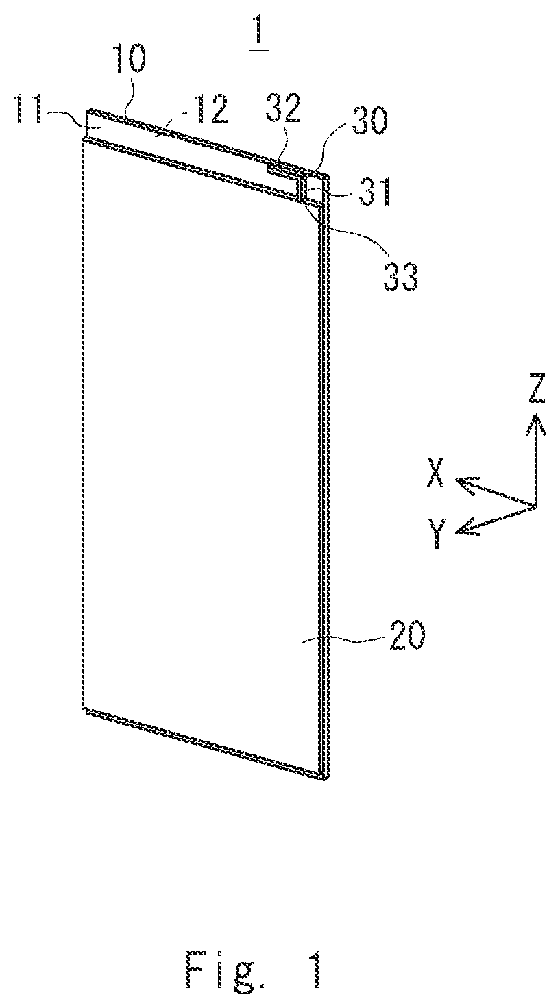
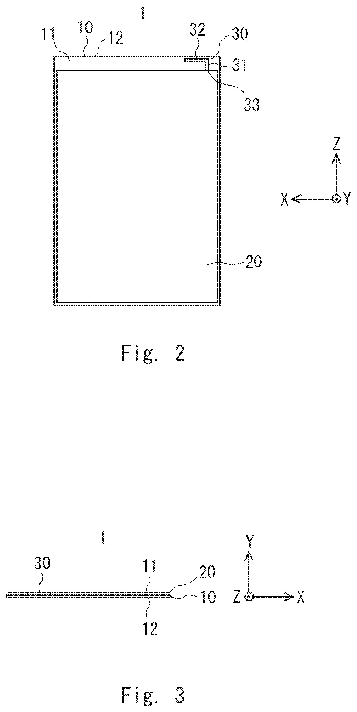
[0046]FIG. 1 is a perspective view illustrating a configuration of a wireless communication device without a parasitic antenna according to the first example embodiment. FIG. 2 is a front view illustrating a configuration of the wireless communication device without the parasitic antenna according to the first example embodiment. FIG. 3 is a top view illustrating a configuration of the wireless communication device without the parasitic antenna according to the first example embodiment. As shown in FIGS. 1-3, a wireless communication device 1 includes a printed board 10, a ground plane 20, and an omnidirectional a...

second example embodiment

[0075]Next, a wireless communication device according to a second example embodiment will be described after a problem of the wireless communication device 1 according to the first example embodiment is described. FIG. 12 is a characteristic diagram illustrating emission patterns of vertically polarized waves and horizontally polarized waves on the XY-plane in the wireless communication device according to the first example embodiment. As shown in FIG. 12, as described above with regard to the wireless communication device 1 according to the first example embodiment, vertically polarized waves have a directivity. On the other hand, the horizontally polarized waves do not have a sufficient directivity.

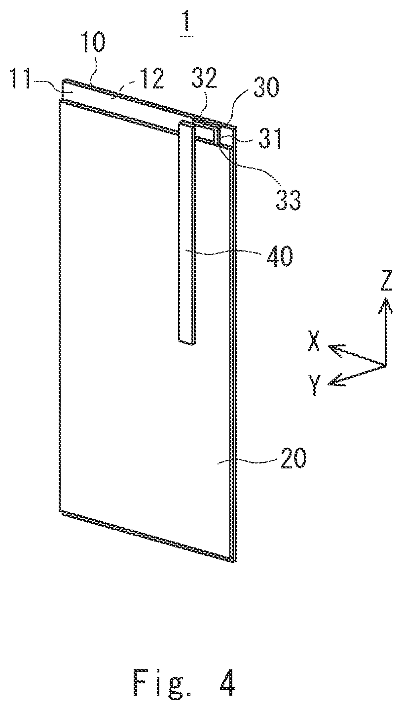
[0076]Next, the wireless communication device according to the second example embodiment will be described. In the wireless communication device according to this example embodiment, a parasitic antenna is bent in the middle thereof and a high-frequency current in the horizontal directi...

third example embodiment

[0088]Next, a wireless communication device according to a third example embodiment will be described. The entire length of the parasitic antenna 40a according to the aforementioned second example embodiment is the wavelength λ.

[0089]Meanwhile, the entire length of the parasitic antenna of the wireless communication device according to this example embodiment is a half-wavelength long, that is, (λ / 2).

[0090]FIG. 18 is a perspective view illustrating the wireless communication device according to the third example embodiment. FIG. 19 is a front view illustrating the wireless communication device according to the third example embodiment. FIG. 20 is a top view illustrating the wireless communication device according to the third example embodiment.

[0091]As shown in FIGS. 18-20, a parasitic antenna 40b of a wireless communication device 3 has an inverted-L shape. The parasitic antenna 40b includes an extending part 43 that is extended in the Z-axis direction and an extending part 44 tha...


PUM


Abstract

A wireless communication device and a wireless communication method capable of improving the directivity of an antenna in a desired direction for a low cost are provided. According to one example embodiment, a wireless communication device includes: a printed board having a substrate surface; a ground plane having a plate shape that is disposed on the substrate surface, connected to the ground potential, and is parallel to the substrate surface; an omnidirectional antenna that is disposed alongside the ground plane on the substrate surface in one direction in a plane parallel to the substrate surface, and is caused to emit radio waves by being supplied with power; and a parasitic antenna that is disposed away from the ground plane in a direction perpendicular to the substrate surface and resonates with the omnidirectional antenna supplied with power.

Description

TECHNICAL FIELD[0001]The present disclosure relates to a wireless communication device and a wireless communication method.BACKGROUND ART[0002]In recent years, in accordance with an increase in rate of wireless communication, wireless communication devices having more favorable wireless communication characteristics have been demanded. As for such wireless communication devices, for example, the demand for home routers that conform to, for example, the Worldwide Interoperability for Microwave Access (WiMAX) standard or Long Term Evolution (LTE) standard has been increasing.[0003]In order to achieve comfortable wireless communication using an omnidirectional antenna in a home router conforming to such a standard, it is required to install the home router at a place with a high radio field intensity as much as possible. In particular, the communication frequency band in the WiMAX standard is in a gigahertz band, which has high frequencies and has a high propagation loss. Consequently,...

Claims


Application Information

Patent Timeline
Patent Type & Authority Applications(United States)
IPC IPC(8): H01Q9/42H01Q1/24H01Q1/48H01Q19/02
CPCH01Q9/42H01Q1/24H01Q1/48H01Q19/02H01Q1/38H01Q1/50H01Q3/00H04W88/14H01Q1/243H01Q19/10
Inventor MIURA, KEN
Owner NEC PLATFORMS LTD
Why Eureka
Try Eureka