Glass antenna for vehicle

a technology for glass antennas and vehicles, applied in the direction of antennas, antenna details, antenna adaptation in movable bodies, etc., can solve the problems of deteriorating the electric wave receiving rate, cracking and snapping, and the reception performance of glass antennas is very poor, so as to improve the directivity of antennas, improve the reception sensitivity, and adapt the effect of antenna length

Inactive Publication Date: 2009-01-22
INFAC YOKOWO
View PDF3 Cites 2 Cited by
  • Summary
  • Abstract
  • Description
  • Claims
  • Application Information

AI Technical Summary

Benefits of technology

[0020]As mentioned above, by the glass antenna for vehicle according to present utility which comprise obliquely tilted part by specific degrees of angle, directivity of antennas can be improved so, it is possible to gain more stable receive sensitivity during moving.
[0021]Also, by the glass antenna for vehicle according to present utility, it is possible to secure suitable antenna length for receiving electric wave frequency at limited area like a side glass of vehicle.

Problems solved by technology

Generally, vehicle antennas are installed in front fender of vehicle or rear quarter in pole type, but this pole type antenna mechanically breaks down frequently, and deteriorates the electric wave receiving rate while moving fast, and because it projects outwardly from the body of vehicle, there is a problem of cracking and snapping.
However, said conventional glass antenna which has a structure of horizontally and vertically crossed conducting wire has good performance at stand still state, but while vehicle's moving, receiving performance of glass antenna deteriorates very much because the receiving sensitivity changes in large range.
Moreover, when said structure of horizontally and vertically crossed conducting wire is composed at narrow glass area like side glass of vehicle, it's hard to form suitable length of conducting wire for receiving electric wave frequency because of limited area.

Method used


Image

  • Glass antenna for vehicle
  • Glass antenna for vehicle
  • Glass antenna for vehicle

Examples


Embodiment Construction

[0025]Hereinafter, the present utility is described in detail with reference to the attached drawings.

[0026]Before the detailed description, it should be noted that the terms used in the present specification and the claims are not to be limited to their lexical meanings, but are to be interpreted to conform with the technical idea of the present utility under the principle that the inventor can properly define the terms for the best description of the utility made by the inventor.

[0027]Therefore, the embodiments and the constitution illustrated in the attached drawings are merely preferable embodiments according to the present utility, and thus they do not express all of the technical idea of the present utility, so that it should be understood that various equivalents and modifications can exist which can replace the embodiments described in the time of the application.

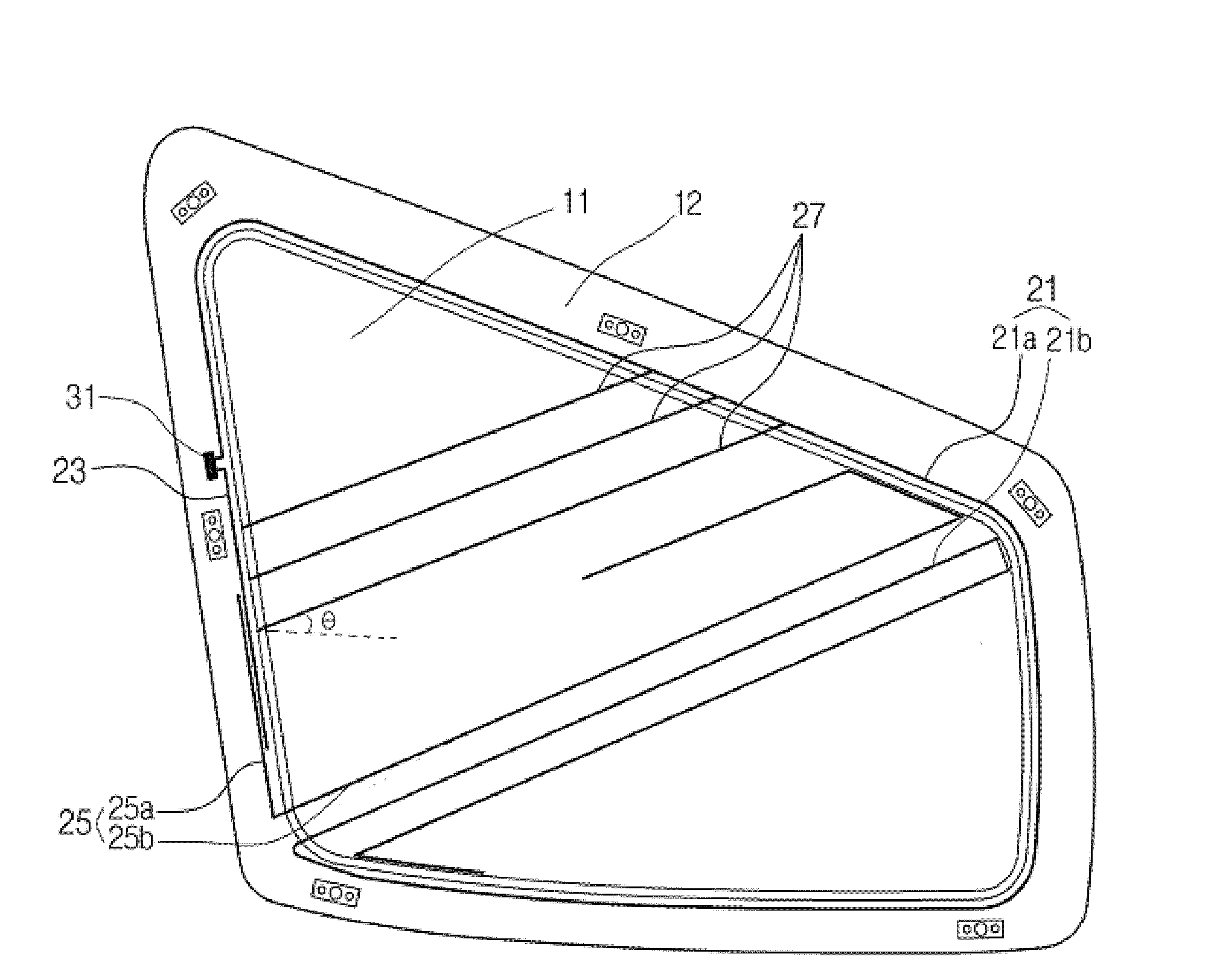
[0028]FIG. 1 is front view of glass antenna for vehicle according to present utility.

[0029]Referring to FIG. 1, g...


PUM


Abstract

A glass antenna for vehicle comprising: a first antenna, a part of which are formed at the edge of vehicle glass to the clockwise direction, and the other part of which is obliquely tilted in the vehicle glass; a second antenna which faces opposite direction to said first antenna; a third antenna, a part of which is parallelly spaced from said second antenna, and the other part of which is obliquely tilted in said vehicle glass; a fourth antenna which is connected with said first antenna and formed plurally tilted in said vehicle glass obliquely; a feed point disposed at the glass frame and connected to said first antenna and second antenna to transmit the signal to receiver. Accordingly, by improving the directivity of said antenna, it's possible to gain more stable receive sensitivity during moving, and antenna length can be extended at limited area.

Description

CROSS REFERENCE[0001]This application claims foreign priority under Paris Convention and 35 U.S.C. § 119 to Korean Patent Application No. 20-2007-0011719, filed Jul. 16, 2007 with the Korean Intellectual Property Office.BACKGROUND OF THE INVENTION[0002]The present utility relates to an glass antenna for vehicle, and more particularly, antenna pattern formed on of vehicle glass obliquely tilted by specific degrees of angle to improve directivity of antennas, and makes it possible to gain more stable receiving sensitivity while moving of the vehicle.[0003]Generally, vehicle antennas are installed in front fender of vehicle or rear quarter in pole type, but this pole type antenna mechanically breaks down frequently, and deteriorates the electric wave receiving rate while moving fast, and because it projects outwardly from the body of vehicle, there is a problem of cracking and snapping.[0004]Therefore, recently, it's universal to compose antenna pattern with thin plate shapes on the ve...

Claims


Application Information

Patent Timeline
Patent Type & Authority Applications(United States)
IPC IPC(8): H01Q1/32
CPCH01Q1/1271H01Q1/32H01Q3/01H01Q9/42H01Q5/30
Inventor SHIN, YONG SHIK
Owner INFAC YOKOWO
Why Eureka
Try Eureka