Peripheral equipment

A technology for peripheral equipment and electronic equipment, applied in signal transmission systems, instruments, electrical digital data processing, etc., can solve the problems of lack of versatility and difficulty in using electronic equipment, and achieve the effect of reducing cost and high versatility

Inactive Publication Date: 2007-09-12
SONY CORP
View PDF1 Cites 0 Cited by
  • Summary
  • Abstract
  • Description
  • Claims
  • Application Information

AI Technical Summary

Problems solved by technology

[0010] In addition, this remote control part must be specially designed for its own associated electronic equipment, so it is difficult to connect this remote control part to various types of electronic equipment for utilization
In short, the problem of lack of generality

Method used


Image

  • Peripheral equipment
  • Peripheral equipment
  • Peripheral equipment

Examples


no. 1 example

[0021] Embodiments of the present invention will be described below with reference to the drawings.

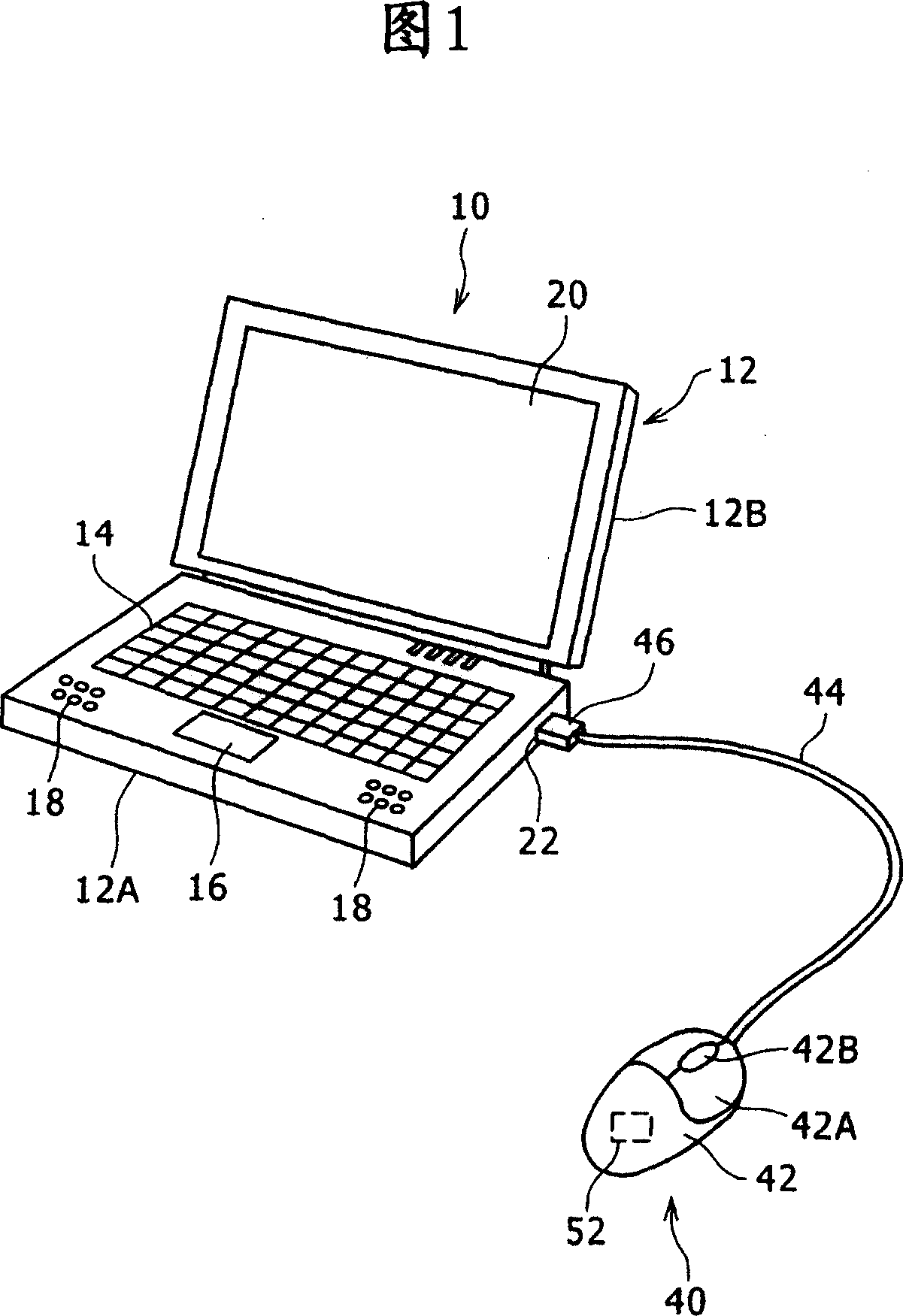
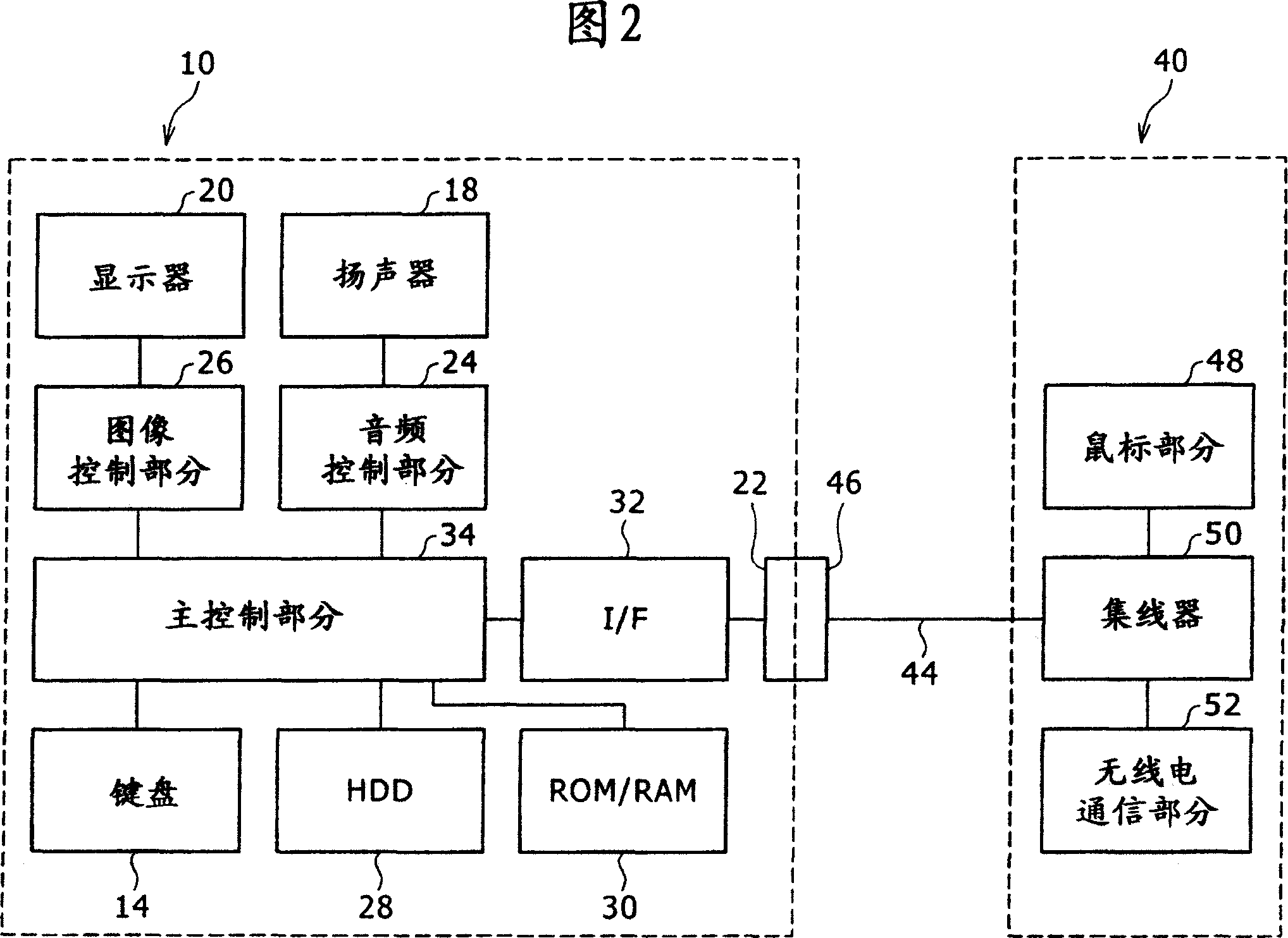
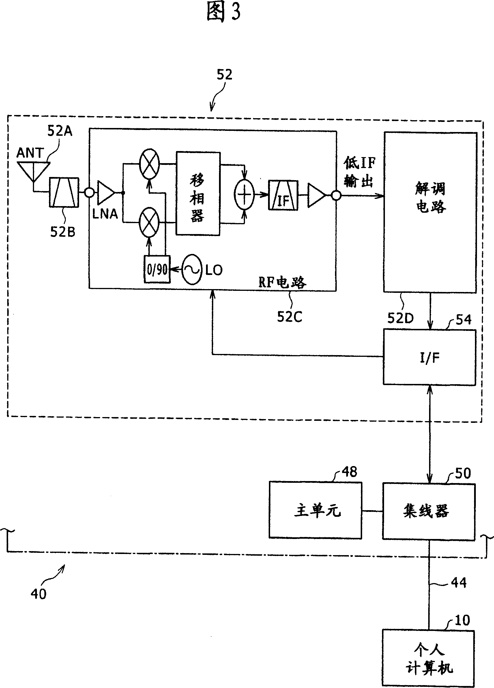
[0022] FIG. 1 shows a personal computer 10 and a mouse 40 connected to each other. FIG. 2 is a block diagram showing the configurations of the personal computer 10 and the mouse 40 . FIG. 3 is a block diagram showing the structure of the mouse 40 .

[0023] The electronic device according to the present invention is a notebook personal computer 10 and the peripheral device according to the present invention is a mouse 40 for operating the personal computer 10 .

[0024] First, the personal computer 10 will be described as follows.

[0025] In FIG. 1 , a personal computer 10 includes a housing 12 . The casing 12 includes a first casing 12A and a second casing 12B connected to one side of the first casing 12A through a hinge. The housing 12 undergoes opening and closing to change between a folded state and an unfolded state. The folded state refers to a state in which the f...

no. 2 example

[0073] Next, a second embodiment of the present invention will be described.

[0074] The difference between the second embodiment and the first embodiment is that the electronic device is a music player 60 and the peripheral device is a remote controller 80 .

[0075] FIG. 4 shows the music player 60 and the remote control 80 connected to each other. FIG. 5 is a block diagram showing the configurations of the music player 60 and the remote control device 80 .

[0076] In this embodiment, the same elements as in the first embodiment are denoted by the same reference numerals as in the first embodiment.

[0077] First, the operation of the music player 60 will be described.

[0078] In FIG. 4 , the music player 60 has a housing 62 . On the operation surface of the housing 62 are provided a display 64 capable of image display, such as a liquid crystal display device, and operation buttons 66 for various operations such as tuning selection, playback, stop, fast forward, rewind...


PUM


Abstract

The invention discloses periphery equipment, which is connected to electronic device with interface cable and is used for exchanging first data with the electronic equipment via the interface cable according to universal interface standard. The periphery equipment includes: wireless communication part for communicating with external in wireless mode, and exchanging second data in relation to wireless communication via the interface cable and the electronic equipment according to universal interface standard.

Description

[0001] Cross-references to related applications [0002] The present application contains subject matter related to Japanese Patent Application JP 2006-063787 filed in the Japan Patent Office on Mar. 9, 2006, the entire content of which is hereby incorporated by reference. technical field [0003] The present invention relates to peripheral devices of electronic equipment. Background technique [0004] An electronic device for reproducing music data recorded on a storage medium such as a memory or a hard disk drive includes a main body and headphones. The main body includes a reproduction section for reproducing music data, a control section for controlling the reproduction section, and an operation section for performing various operations. The headphones are connected to the main body through a cable, and output sound according to the audio signal output from the reproduction section. [0005] As one such electronic equipment, there is an electronic equipment including i...

Claims


Application Information

Patent Timeline
Patent Type & Authority Applications(China)
IPC IPC(8): G08C17/00G08C17/02G06F3/033H04B5/00G06F3/0354
CPCG06F1/1632G06F3/03543
Inventor 横木清忠高松宏行森康平沟吕木上朝仓健二
Owner SONY CORP
Why Eureka
Try Eureka