Method and apparatus for transmitting/receiving signals in a microwave system

a microwave system and transmission method technology, applied in multiplex communication, optics, instruments, etc., can solve the problems of increasing the design difficulty and increasing the production cost of the cable, and achieve the effect of simplifying the transmission process, reducing the cost of if-rf design, and simplifying the complexity of the if-rf transmitting/receiving process

Inactive Publication Date: 2013-02-26
HUAWEI TECH CO LTD
View PDF33 Cites 0 Cited by
  • Summary
  • Abstract
  • Description
  • Claims
  • Application Information

AI Technical Summary

Benefits of technology

[0022]Advantageous effects of the technical solutions according to the embodiments of the present invention are presented below. In comparison with the separated design of the indoor unit and the outdoor unit in the prior art microwave technology, the integrated design of the microwave system greatly simplifies the complexity of the IF-RF transmitting / receiving processes in the separated design of the indoor unit and the outdoor unit, reduces 1˜2 frequency mixing stages, simplifies the designs of the transmission and separation filter and the amplifier, hence reduces the cost of IF-RF design, decreases the loss of signal-to-noise ratio brought about by signal combining and branching in the separated design of the indoor unit and the outdoor unit, increases the reception sensitivity of the system by about 1 dB, achieves the objectives of lowering system consumption at the same time of lowering circuit complexity, realizes application of large capacity microwave due to the use of optical fibers for transmitting and receiving signals, and greatly saves production cost.
of the technical solutions according to the embodiments of the present invention are presented below. In comparison with the separated design of the indoor unit and the outdoor unit in the prior art microwave technology, the integrated design of the microwave system greatly simplifies the complexity of the IF-RF transmitting / receiving processes in the separated design of the indoor unit and the outdoor unit, reduces 1˜2 frequency mixing stages, simplifies the designs of the transmission and separation filter and the amplifier, hence reduces the cost of IF-RF design, decreases the loss of signal-to-noise ratio brought about by signal combining and branching in the separated design of the indoor unit and the outdoor unit, increases the reception sensitivity of the system by about 1 dB, achieves the objectives of lowering system consumption at the same time of lowering circuit complexity, realizes application of large capacity microwave due to the use of optical fibers for transmitting and receiving signals, and greatly saves production cost.

Problems solved by technology

Moreover, in order to ensure IF transmission / reception interval, the transmission / reception frequency may have to be markedly increased, while increase of the frequency means more attenuation of the cable, so that the prior art separate design of the indoor unit and the outdoor unit in application to such large capacity microwave not only increases the difficulty in design, but also inevitably requires less attenuation of the IF cable due to more attenuation of the signal caused by increase in the IF.
Consequently, stricter requirement is called for the cable, and the production cost of the cable is hence increased.

Method used


Image

  • Method and apparatus for transmitting/receiving signals in a microwave system
  • Method and apparatus for transmitting/receiving signals in a microwave system
  • Method and apparatus for transmitting/receiving signals in a microwave system

Examples


embodiment 1

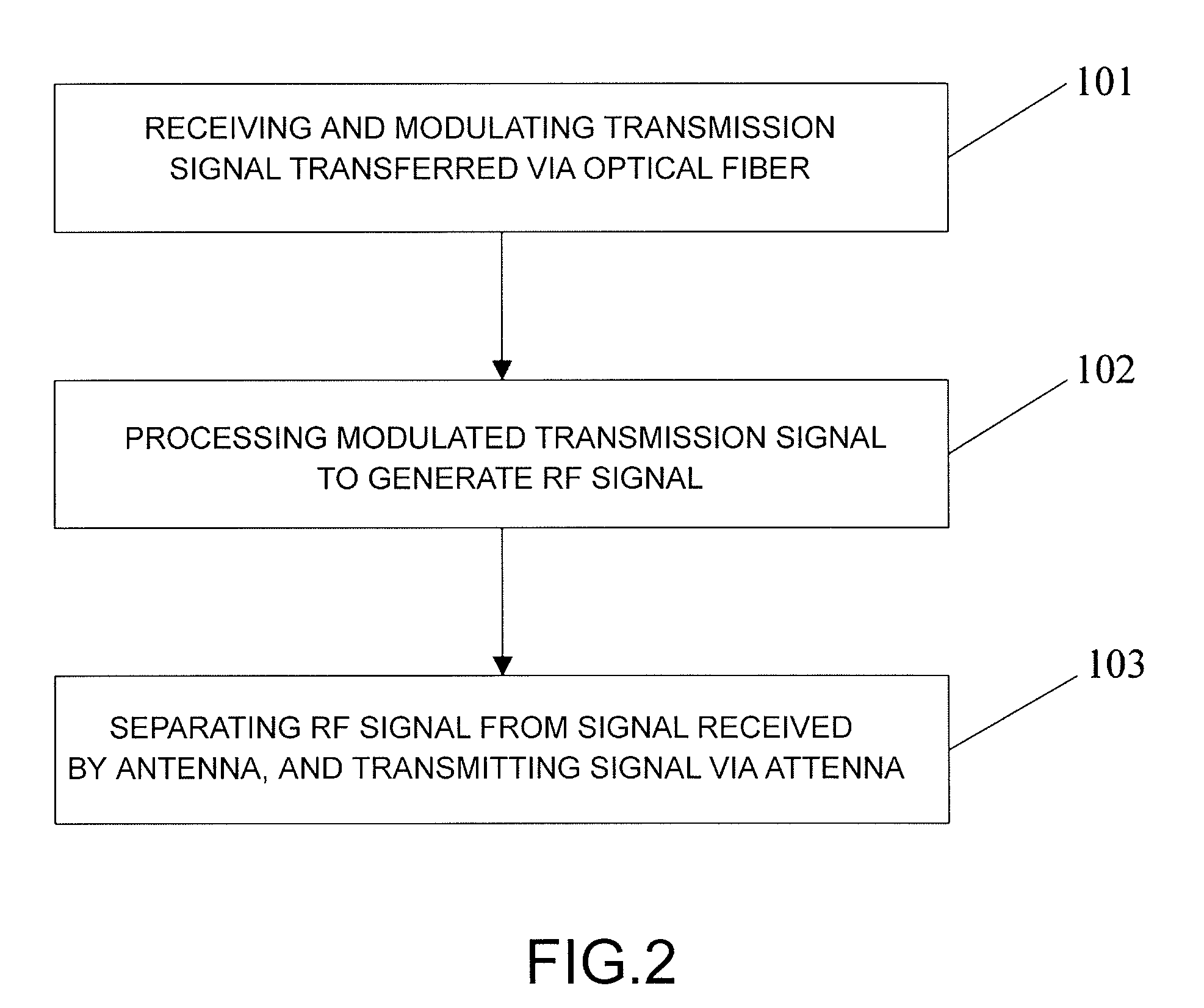
[0031]Referring to FIG. 2, the embodiment of the present invention provides a method for transmitting a signal in a microwave system, which method comprises the following steps:

[0032]Step 101: receiving and modulating a transmission signal transferred via an optical fiber.

[0033]Specifically, the transmission signal transferred via the optical fiber includes a traffic signal and a control signal. The traffic signal is extracted and then modulated.

[0034]Step 102: processing the modulated transmission signal to generate RF signal.

[0035]In such processing, the signal firstly undergoes IF transmission processing including digital-to-analog conversion, analog IQ modulation, filtering and amplification, and then undergoes microwave RF processing including up-conversion, filtering and amplification.

[0036]Step 103: separating the RF signal to be transmitted from a signal received via an antenna, and transmitting the separated RF signal via the antenna.

[0037]Specifically, a duplexer is used t...

embodiment 2

[0043]Referring to FIG. 3, the embodiment of the present invention provides a method for receiving a signal in a microwave system, which method comprises:

[0044]Step 201: separating a signal received via an antenna from a signal to be transmitted.

[0045]Specifically, a duplexer may be used to separate the signal received via the antenna from the signal to be transmitted. The function of the duplexer is to separate the received signal from the signal to be transmitted to guarantee that reception and transmission normally operate at the same time. The duplexer consists of two sets of bandpass filters having different frequencies to prevent the native received signal from being transmitted to the transmitter.

[0046]Step 202: processing the received signal after being separated to generate IF signal.

[0047]In such processing, the signal firstly undergoes microwave RF reception processing including down-conversion, amplification and filtering, and then undergoes IF reception processing inclu...

embodiment 3

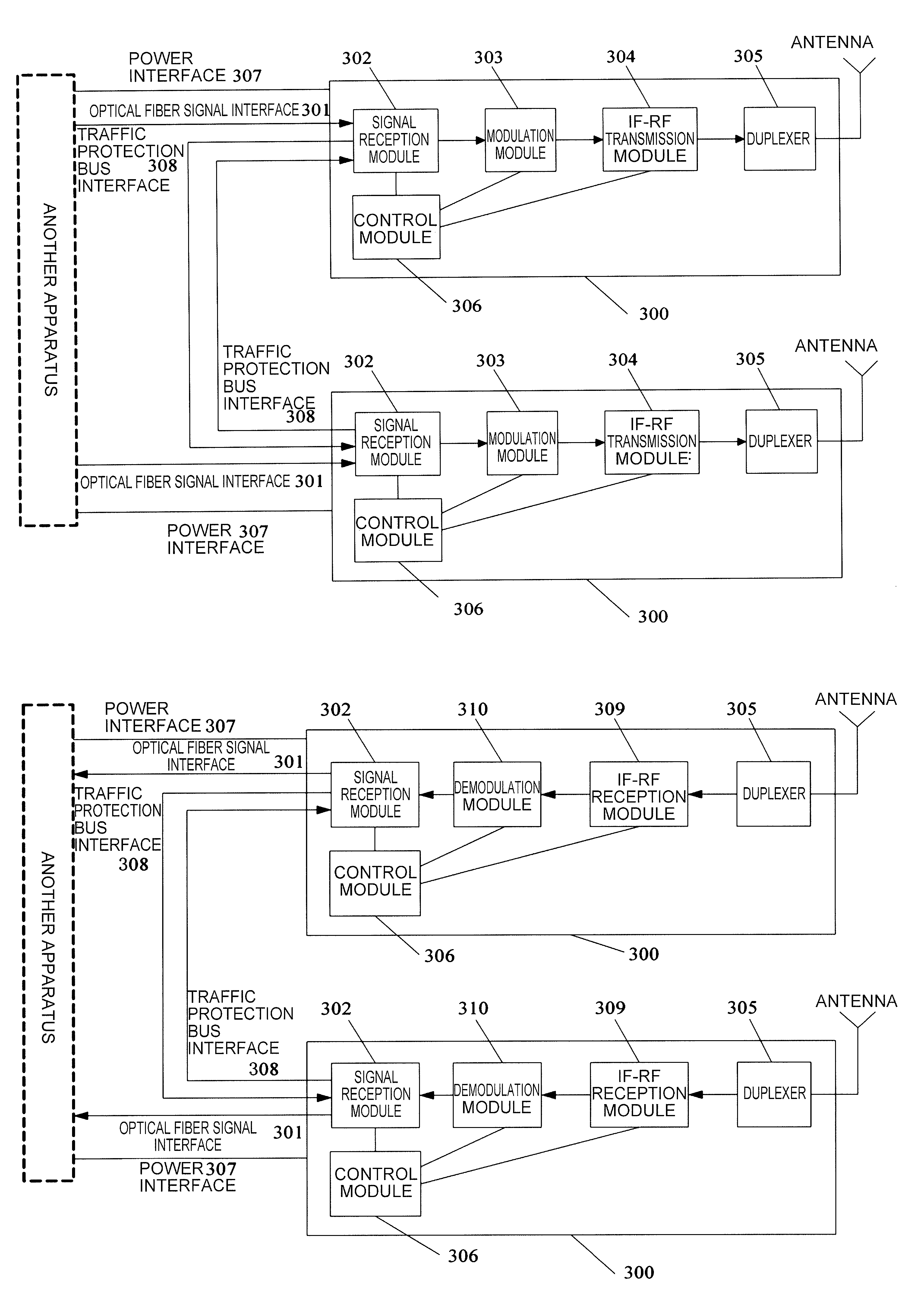
[0055]Referring to FIG. 4, the embodiment of the present invention provides an apparatus 300 for transmitting a signal in a microwave system. The apparatus 300 is adapted to comprise an optical fiber signal interface 301, a signal reception module 302, a modulation module 303, an IF-RF transmission module 304, a duplexer 305, a control module 306 and a power interface 307.

[0056]The signal reception module 302 is adapted to receive a transmission signal sent from another apparatus via the optical fiber signal interface 301, and send the received transmission signal to the modulation module 303.

[0057]Specifically, the transmission signal transferred via the optical fiber includes a traffic signal and a control signal. The signal reception module 302 is adapted to perform extraction on the transmission signal, and transmit the extracted traffic signal to the modulation module 303.

[0058]The modulation module 303 is adapted to modulate the transmission signal sent from the signal recepti...


PUM


Abstract

This invention discloses a method and an apparatus for transmitting / receiving signals in a microwave system, and pertains to the field of communications. The transmitting method comprises receiving and modulating a transmission signal transmitted via an optical fiber; processing the modulated transmission signal to generate RF signal; and separating the RF signal to be transmitted from a signal received via an antenna, and transmitting the separated RF signal via the antenna. The receiving method comprises separating a signal received via an antenna from a signal to be transmitted; processing the received signal after being separated to generate IF signal; demodulating the generated IF signal; and transmitting the received signal after being demodulated via an optical fiber. The transmitting / receiving apparatus comprises an optical fiber signal interface, a signal reception module, a modulation module, an IF-RF transmission module, a duplexer, a control module and a power interface. Use of the optical fiber to transmit the transmission signal and the received signal according to the present invention makes it possible for application of large capacity microwave and also greatly saves production cost.

Description

CROSS-REFERENCE TO RELATED APPLICATION[0001]This application claims priority to Chinese Patent Application No. 200810186118.2, filed on Dec. 17, 2008, which is hereby incorporated by reference in its entirety.FIELD OF THE INVENTION[0002]The present invention relates to the field of communications, and more particularly to a method and an apparatus for transmitting / receiving signals in a microwave system.BACKGROUND OF THE INVENTION[0003]The most conventional system design in a microwave system includes an indoor unit and an outdoor unit mounted separately from each other and connected via an intermediate frequency (IF) cable to each other. Signals transmitted over the cable include a transmission / reception IF signal, a transmission / reception control signal and a 48 V power signal. Refer to FIG. 1, which shows the operational principle of the prior art. As shown in FIG. 1, in the transmission direction, after the transmission data is modulated by a modulation / demodulation unit 10 in t...

Claims


Application Information

Patent Timeline
Patent Type & Authority Patents(United States)
IPC IPC(8): H04B10/00H04B10/032H04B10/2575
CPCH04B10/032H04B10/25759
Inventor ZHAO, GUIXUE
Owner HUAWEI TECH CO LTD
Why Eureka
Try Eureka