
Routing procedure for a communication system

Inactive Publication Date: 2008-08-19
NOKIA CORP
View PDF18 Cites 14 Cited by
  • Summary
  • Abstract
  • Description
  • Claims
  • Application Information

AI Technical Summary

Benefits of technology

[0016]In one embodiment of the present invention there is a mechanism whereby a MOCN routing procedure, and especially the rejection of a registration request can be carried out in a controlled manner so that unnecessary rerouting and registration attempts can be avoided.
[0022]Another embodiment of the present invention includes, for example, a mechanism that enables a MOCN to behave as a single network from the terminal point of view in the context of roaming. In other words, the present invention can, for example, assure that the MOCN behaves consistently in all circumstances so that rerouting can be hidden from the terminal and the MOCN appears in all circumstances as a single network from the terminal point of view.

Problems solved by technology

One problem with the current MOCN networks relates to the rejection of service in a situation in which none of the Core Networks (i.e. operators) are able to provide service to a particular subscriber.
As there is currently no mechanism for handling these kinds of situations in the Radio Access Network, the Radio Access Network may alternately, upon receiving the service rejection from the last Core Network, release the signaling connection to the user terminal, without properly indicating the reason for the release.
The above problem typically exists when the subscriber tries to register with the network.

Method used


Image

  • Routing procedure for a communication system
  • Routing procedure for a communication system
  • Routing procedure for a communication system

Examples


first embodiment

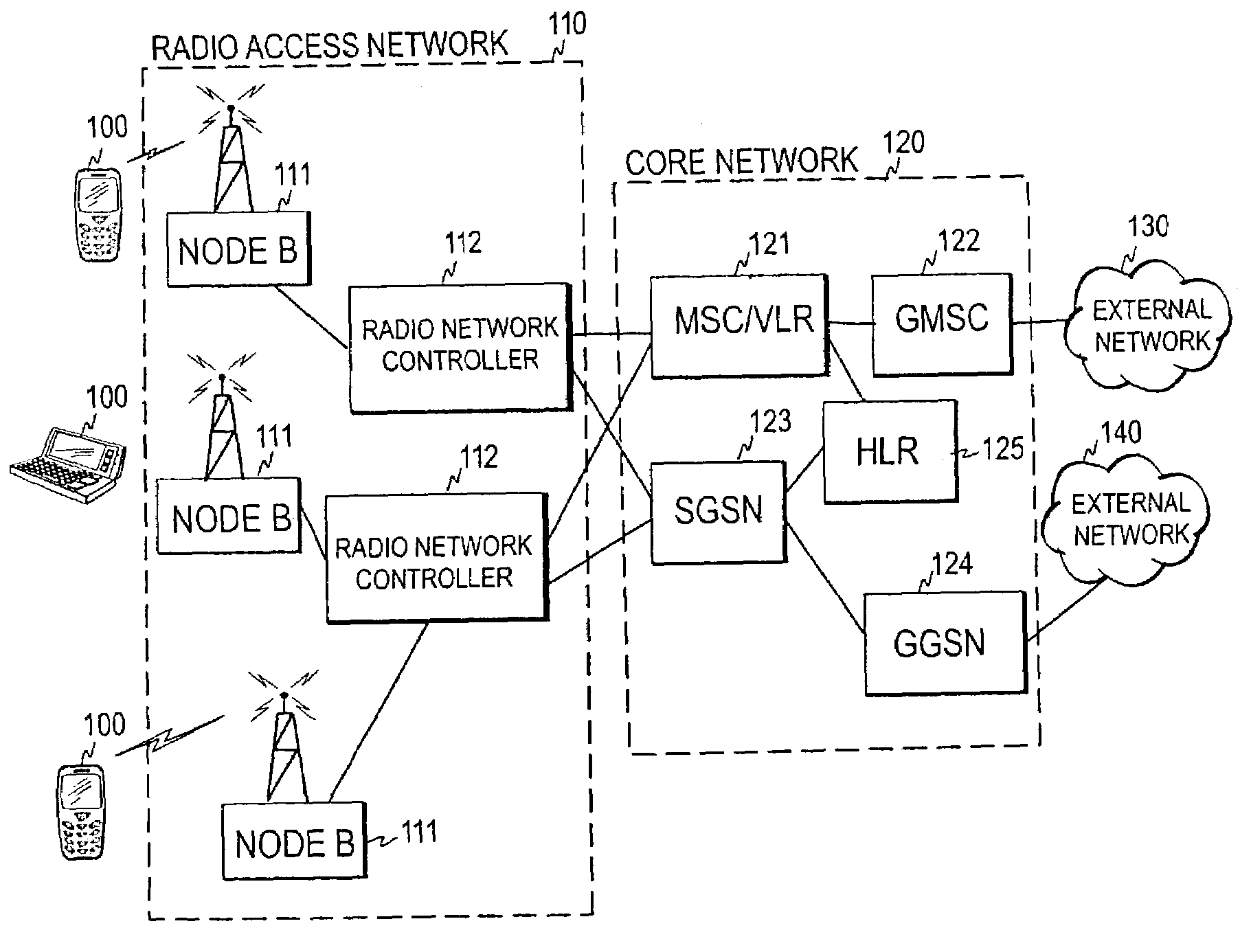
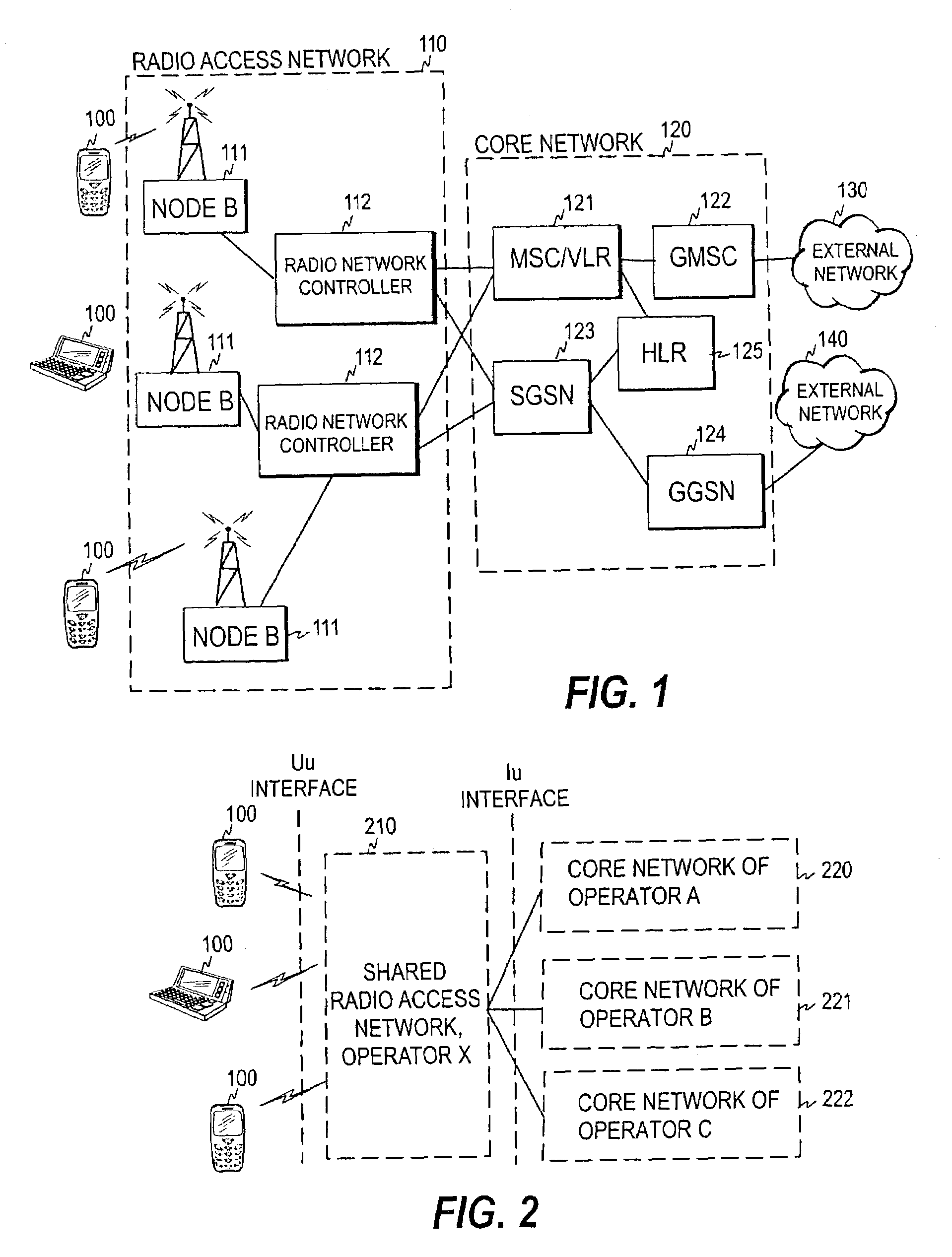
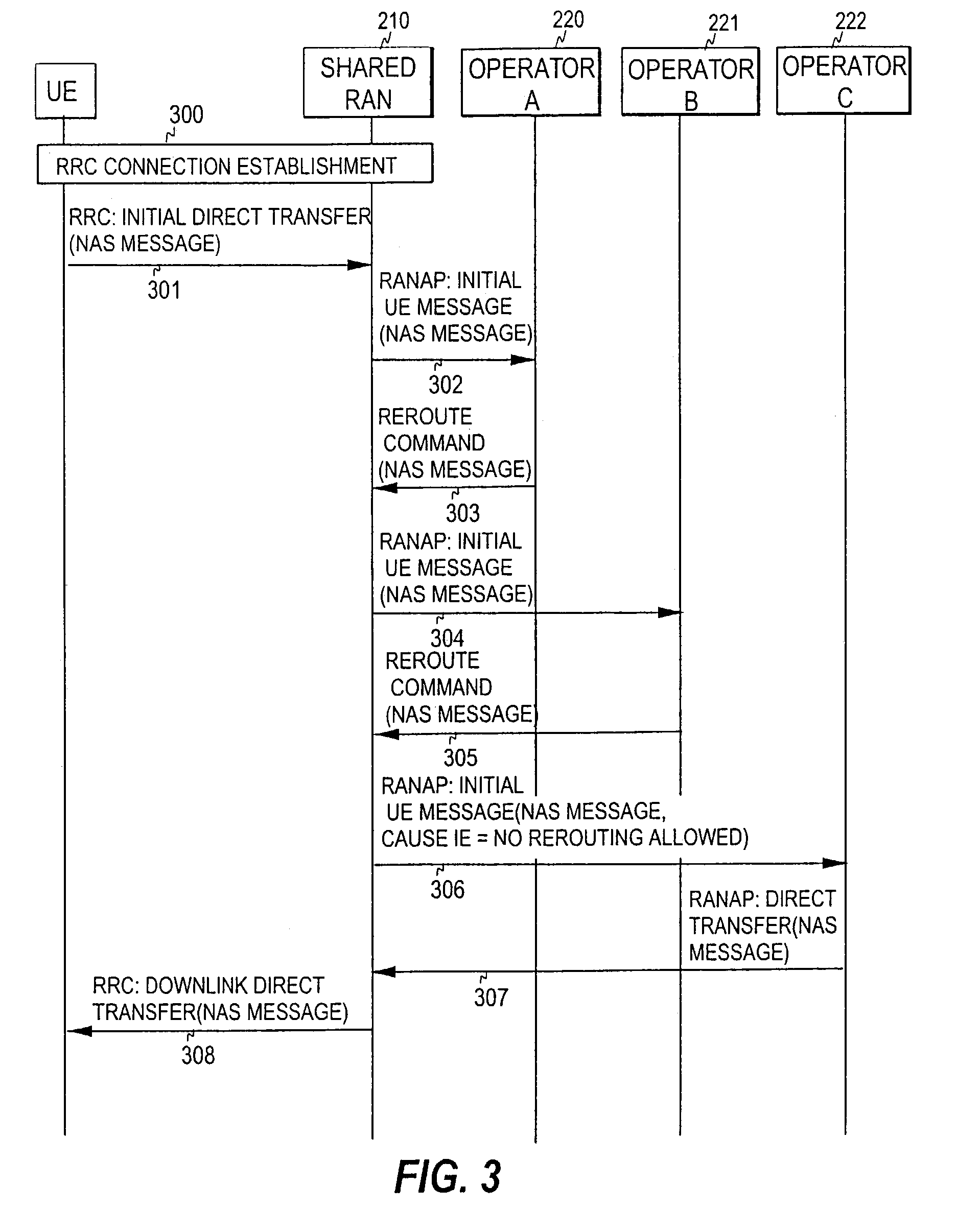
[0042]FIG. 3 illustrates the invention by showing the message exchange between the different entities in FIG. 2. As mentioned above, the RRC can be used in UMTS for connecting the terminal with the Radio Access Network. Therefore, when a user enters the network, an RRC connection must first be established across the Uu interface (step 300). The terminal then uses the initial direct transfer procedure to carry the initial message, which is a Non-Access Stratum (NAS) message to be transferred transparently through the RAN to the CN, over the radio interface to the RAN (step 301). The NAS message is the above-mentioned registration request, which in connection with registration may be a Location Updating Request, a Routing Area Update Request, or an attach message (PS attach or CS attach), for example.

[0043]The RNC then initiates the Initial UE message procedure according to the RANAP protocol, and forwards the NAS message first to the Core Network 220 of operator A in an initial UE me...

second embodiment

[0048]To avoid the above-described situation, a Core Network informs the next attempted Core Network the reason why the registration request was rejected. This may be implemented by adding to the reroute command a cause value, indicating why rerouting has taken place. FIG. 5 illustrates this embodiment, by showing the message exchange between the different entities in FIG. 2. In this embodiment, each reroute command sent to the RNC by the Core Network includes a cause value indicating why the Core Network rejected the request (compare steps 503 and 505). The RNC forwards the cause value received from the Core Network to the next Core Network in the initial UE message, whereby each Core Network that receives the registration request also receives the information why the request was previously rejected by one or more Core Networks (compare steps 504 and 506). It is to be noted here that the cause values can be used in the embodiment of FIG. 3, in the embodiment of FIG. 4, or in the ab...


PUM


Abstract

A mechanism for performing routing in a communication system including a radio access network and a plurality of core networks connected to the radio access network. In order to accomplish a mechanism whereby the routing of a registration request to a serving core network, and also the rejection of a registration request, can be carried out in a controlled manner, a core network is first selected for a registration request received. The registration request is then forwarded to the selected core network and, in response to at least one predetermined criterion being fulfilled, the selected core network is notified that the registration request is to be served by that core network, i.e. that the registration request cannot be rerouted to another core network.

Description

REFERENCE TO RELATED APPLICATIONS[0001]This application claims priority of U.S. Provisional Patent Application Ser. No. 60 / 447,752, entitled “Routing Procedure for a Communication System” filed on Feb. 19, 2003, the contents of which are hereby incorporated by reference.BACKGROUND OF THE INVENTION[0002]1. Field of the Invention[0003]The invention relates generally to a communication system where a plurality of Core Networks (CNs) shares a common Radio Access Network (RAN). More specifically, the invention relates to a routing procedure in a system of the above-mentioned type. Since the Core Networks are typically operated by different operators, the system is termed a Multi-Operator Core Network (MOCN) in this context. Routing here refers generally to a process during which the RAN, in response to an initial message originated from a user terminal, selects a Core Network for the user terminal.[0004]2. Description of the Related Art[0005]The high price of the licenses for 3rd generat...

Claims


Application Information

Patent Timeline
IPC IPC(8): H04Q7/20H04W8/18H04W48/18H04W60/00H04W76/04H04W88/10H04W92/02H04W92/14
CPCH04W48/18H04W60/00H04W8/18H04W92/14H04W88/10H04W92/02H04W76/04H04W76/20
Inventor KAURANEN, KARI P.HULKKONEN, TONY
Owner NOKIA CORP
Learn More