
Method and apparatus for migrating data and automatically provisioning a target for the migration

Active Publication Date: 2008-08-19
EMC IP HLDG CO LLC
View PDF53 Cites 62 Cited by
  • Summary
  • Abstract
  • Description
  • Claims
  • Application Information

AI Technical Summary

Benefits of technology

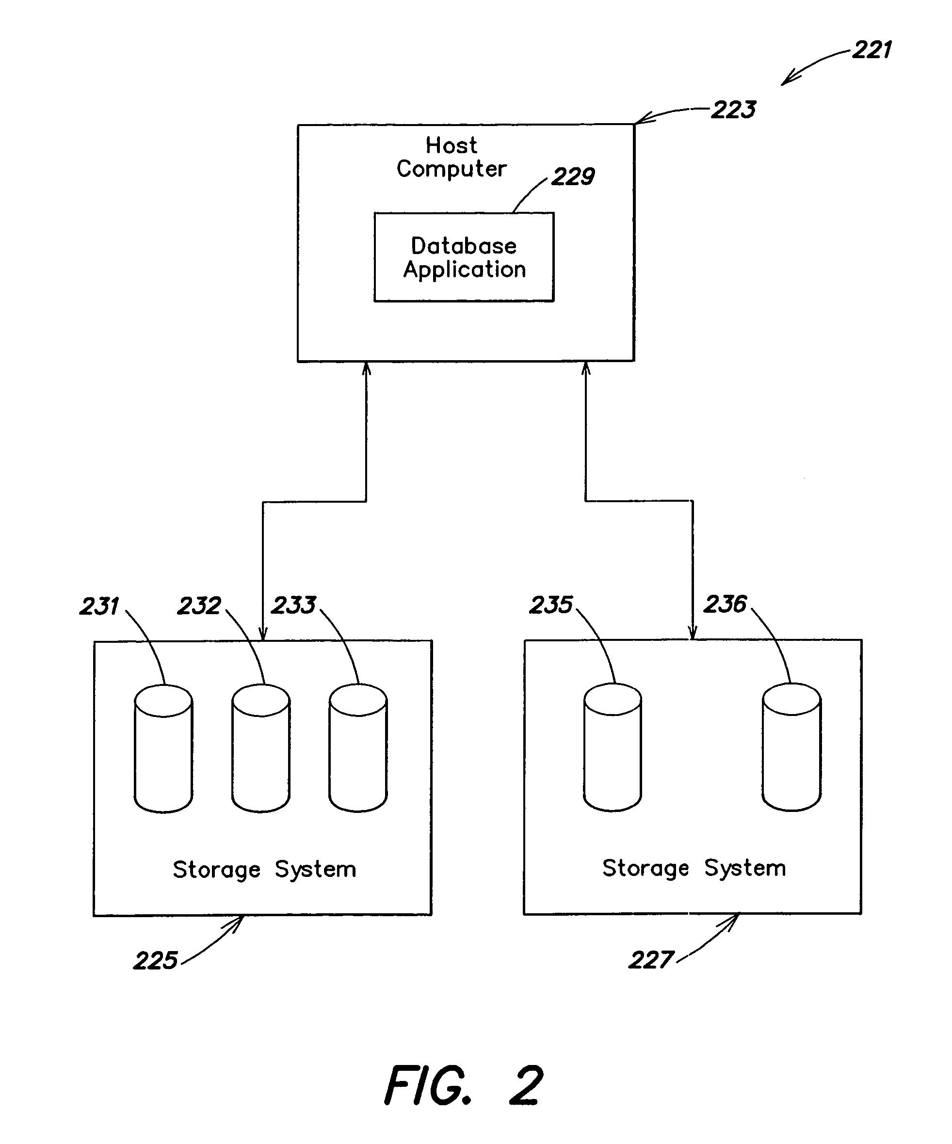
[0021]In still another embodiment, an apparatus is provided for migrating a logical object comprising a plurality of logically associated data elements from at least one first logical volume to at least one second logical volume in a computer system including at least one host computer and at least one storage system, each of the logical volumes being presented by the at least one storage system to the at least one host computer and each being perceived by the at least one host computer as corresponding to a physical storage device, the logical object storing data accessible to an application program executing on the at least one host computer. The apparatus comprises at least one processor programmed to: move the data stored within the logical object from the at least one first logical volume to the at least one second logical volume; after completion of the move of the data, automatically service access requests from the application program directed to the logical object from the at least one second logical volume; retire the at least one first logical volume upon automatically servicing access requests from the application program directed to the logical object from the at least one second logical volume; and maintain availability of the logical object to service access requests from the application program during the move of the data.

Problems solved by technology

Data migrations are often complicated and problematic exercises.
Depending on the size of the data set, applications can be offline for lengthy periods, leading to a loss of productivity, and opportunity cost associated with not having the data set available for important business functions.
Migrations typically are manual labor-intensive efforts, and are therefore error-prone, costly and involve redirecting human resources to the migration.
This step is typically very time-consuming and labor-intensive, and thus expensive.
Synchronization is often the most time consuming of the four steps, and usually requires that applications accessing the data be taken offline (i.e., refused access to the data) while the step is performed.
Again, this conventionally requires human intervention and may require rebooting of the host computer(s) that access the data set.

Method used


Image

  • Method and apparatus for migrating data and automatically provisioning a target for the migration
  • Method and apparatus for migrating data and automatically provisioning a target for the migration
  • Method and apparatus for migrating data and automatically provisioning a target for the migration

Examples


Embodiment Construction

[0046]Several embodiments of the present invention are directed to improved methods and apparatus for migrating data in a computer system. In accordance with one of these embodiments, various aspects of the migration process are automated, thereby reducing the need for human intervention and the associated costs, delay and potential for error associated therewith.

[0047]In accordance with another embodiment of the present invention, the data set being migrated need not be taken off line during the migration, thereby alleviating one of the major downsides to conventional migration techniques.

[0048]In accordance with yet another embodiment of the present invention, the ability is provided to “undo,” or revert from, a migration. In this respect, and as discussed above, it should be appreciated that migrations are often prone to error. Occasionally, errors are not detected until after the data set has actually been moved, the system has been reconfigured and the applications that access ...


PUM


Abstract

Methods and apparatus for migrating a logical object. In one embodiment, a migration is performed by automatically determining the source location(s) of the logical object, moving the data stored therein to a target location while maintaining the availability of the data at the source location to an application program, and automatically servicing access requests from the application program at the target location after moving the data. In another embodiment, a migration is performed by automatically provisioning target location(s) to store a logical object, moving the data in the logical object to the target location(s) while maintaining its availability to an application program, and automatically servicing access requests from the application program at the target location after moving the data. In a further embodiment, a migration is performed by moving the data within a logical object from a source logical volume to a target logical volume, automatically servicing access requests from an application program at the target logical volume after moving the data, and retiring the source logical volume.

Description

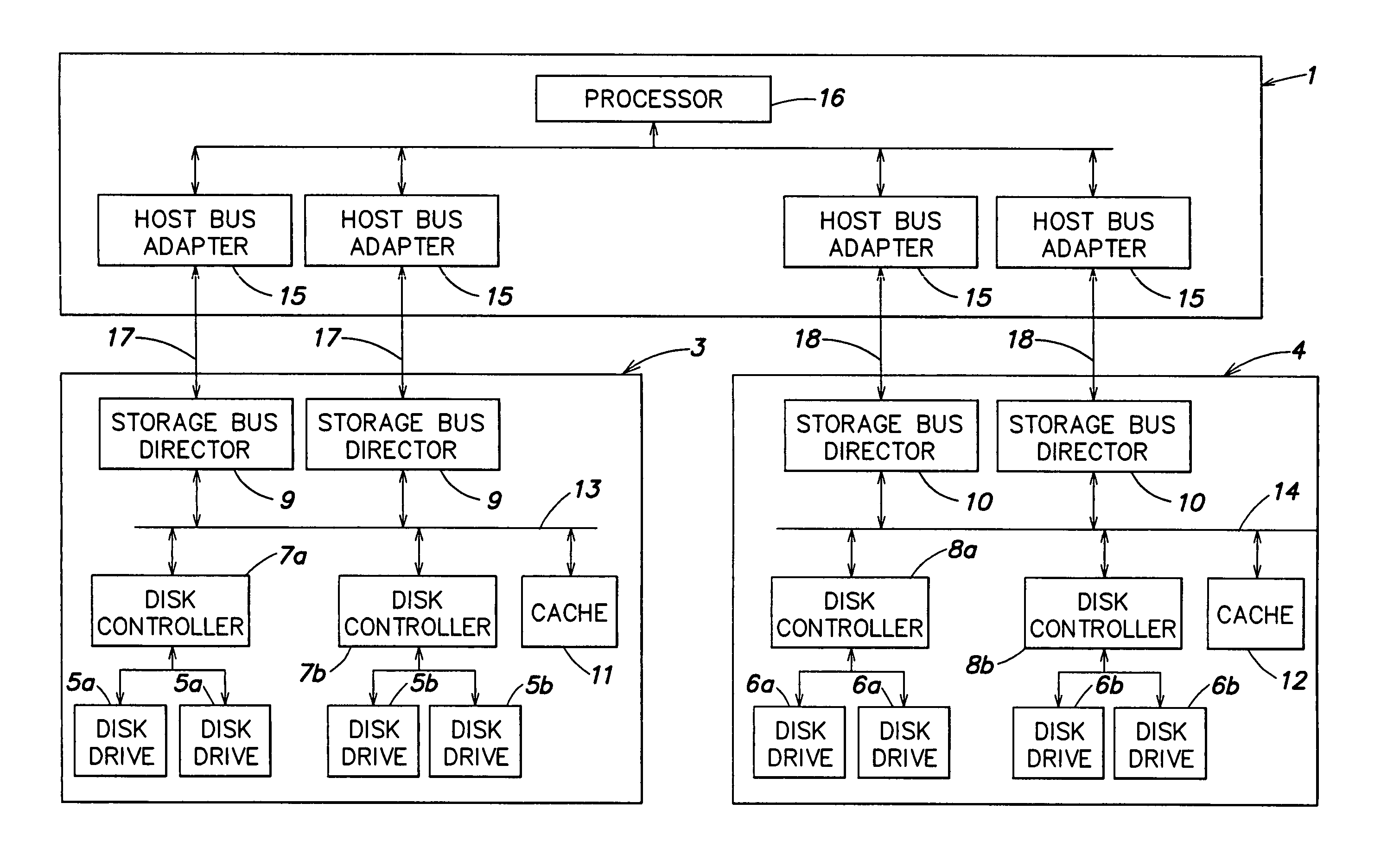
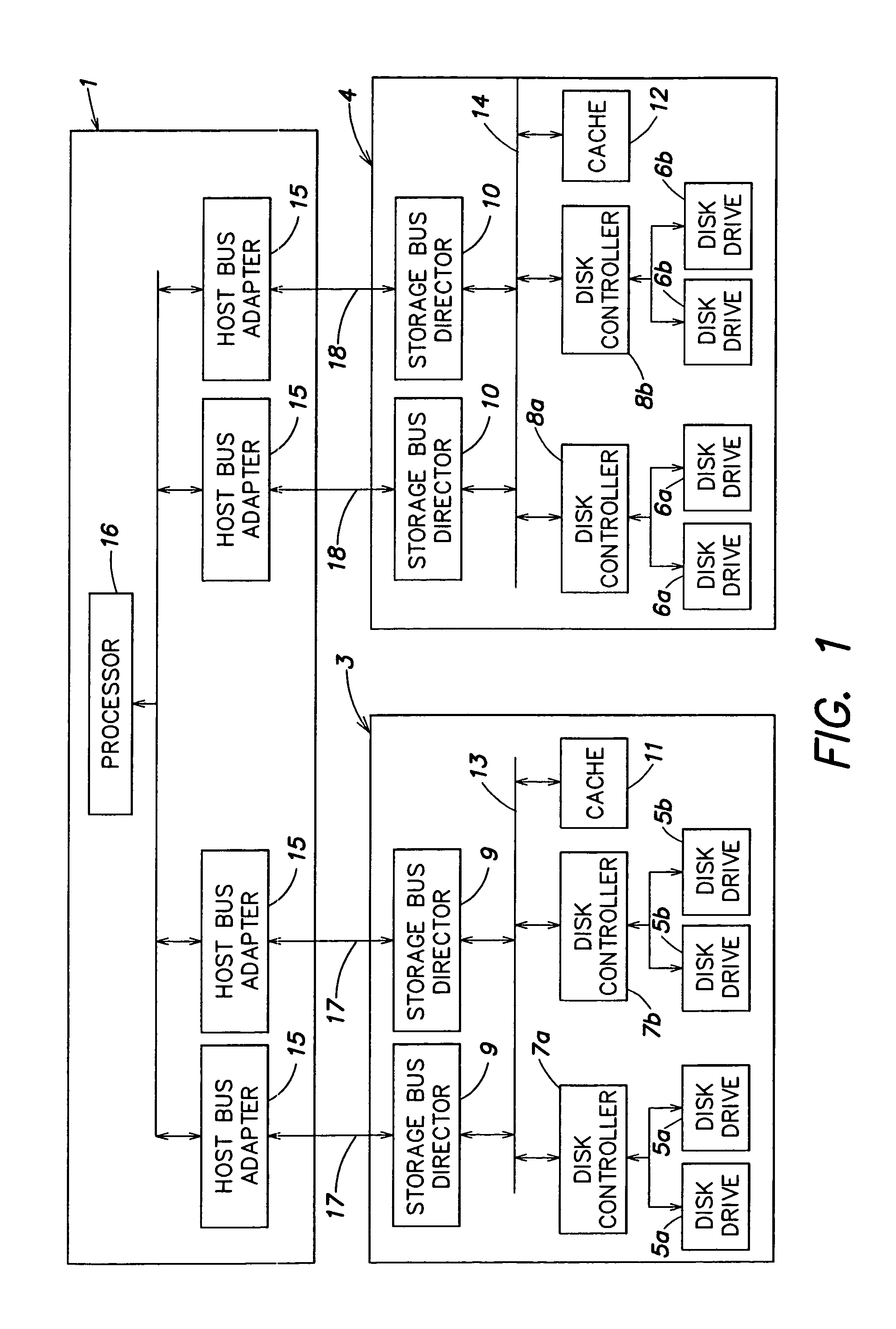
FIELD OF THE INVENTION[0001]This invention relates generally to the field of computer systems, and more particularly, to methods and apparatus for migrating data in a computer system.DESCRIPTION OF THE RELATED ART[0002]Many computer systems include one or more host computers, and one or more storage systems that store data used by the host computers. An example of such a computer system including a host computer 1 and two storage systems 3 and 4 is shown in FIG. 1.[0003]The storage systems 3, 4 include a plurality of disk drives (5a-5b or 6a-6b) and a plurality of disk controllers (7a-7b or 8a-8b) that respectively control access to the disk drives. A plurality of storage bus directors (9, 10) control communication with host computer 1 over communication buses (17, 18). Each storage system 3, 4 further includes a cache 11, 12 to provide improved storage system performance. In particular, when the host computer 1 executes a read from one of the storage systems 3, 4, the storage syste...

Claims


Application Information

Patent Timeline
IPC IPC(8): G06F13/14
CPCG06F3/0614G06F3/0635G06F3/067G06F3/0647G06F11/2071G06F11/1471
Inventor TODD, STEPHEN J.BLUMENAU, STEVEN M.CAKELJIC, ZORAN
Owner EMC IP HLDG CO LLC
Learn More