Support structure for pedal of vehicle

a technology for supporting structures and pedals, which is applied to mechanical control devices, roofs, tractors, etc., can solve the problems of affecting the driver's foot or compressing the foot space of the driver, and affecting the normal braking operation of the driver, so as to achieve reliable forcible displacement and normal braking operation. the effect of operation

Inactive Publication Date: 2008-08-26
AUTO TECH CORP +1
View PDF21 Cites 19 Cited by
  • Summary
  • Abstract
  • Description
  • Claims
  • Application Information

AI Technical Summary

Benefits of technology

[0009]One object of the present invention is to provide a support structure for a pedal of a vehicle which provides reliable forcible displacement of a pedal in the direction to the front of the vehicle.
[0010]Another object of the present invention is to provide a support structure for a pedal of a vehicle which provides reliable forcible displacement of a pedal in the direction to the front of the vehicle, both when the pedal is not in its operated condition and when the pedal is in its operated condition.
[0011]Another object of the present invention is to provide a support structure for a pedal of a vehicle which provides reliable forcible displacement of the pedal in the direction to the front of the vehicle, depending on the amount of crashing force exerted on the vehicle.

Problems solved by technology

In vehicle accidents such as front end collisions, the engine of the vehicle is forced rearwardly by a large load force affecting the front portion of the vehicle which causes the brake pedal and / or the clutch pedal attached to the dash-board lower panel to be pushed into the cabin of the vehicle, thereby interfering with the driver's feet or compressing the foot space of the driver.
However, since the escape structures are not integrated and the pivotable link is connected both to the pedal bracket and to the member connected between pillars, it can be difficult for the pivotable link to be pivoted, especially when the moving direction of the pedal bracket is varied vertically and / or horizontally due to variability of the parts or deforming conditions of the vehicle dash panel.
Furthermore, vibration of the member connected between the pillars causes the vibration of the pedal, which makes it difficult for the driver to feel the pedal.
Also, because the pivotable link is connected both to the vehicle dash panel and to the member connected between the pillars, the assembling operation is complex.
On the other hand, because deformation of the pedal bracket is utilized for pivoting the stop means, which pivoting action releases the engagement between the foot pedal and the support means, there is some risks that the escape structure will not operate properly, depending on the deforming conditions of the pedal bracket.

Method used


Image

  • Support structure for pedal of vehicle
  • Support structure for pedal of vehicle
  • Support structure for pedal of vehicle

Examples


fourth embodiment

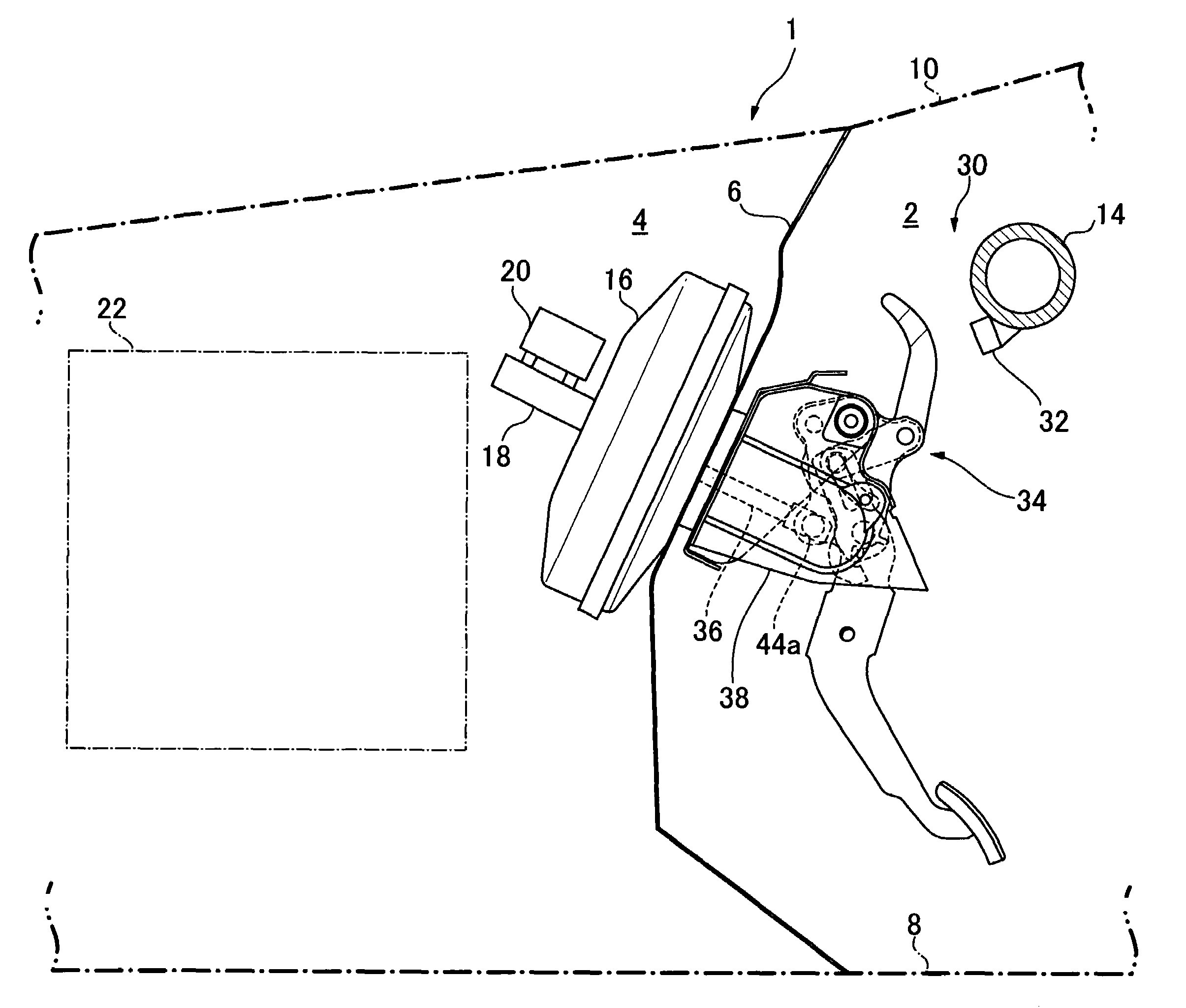
[0252]Now, with reference to the FIGS. 21 to 25, the support structure for a brake pedal of a vehicle in accordance with the present invention will be described in detail.

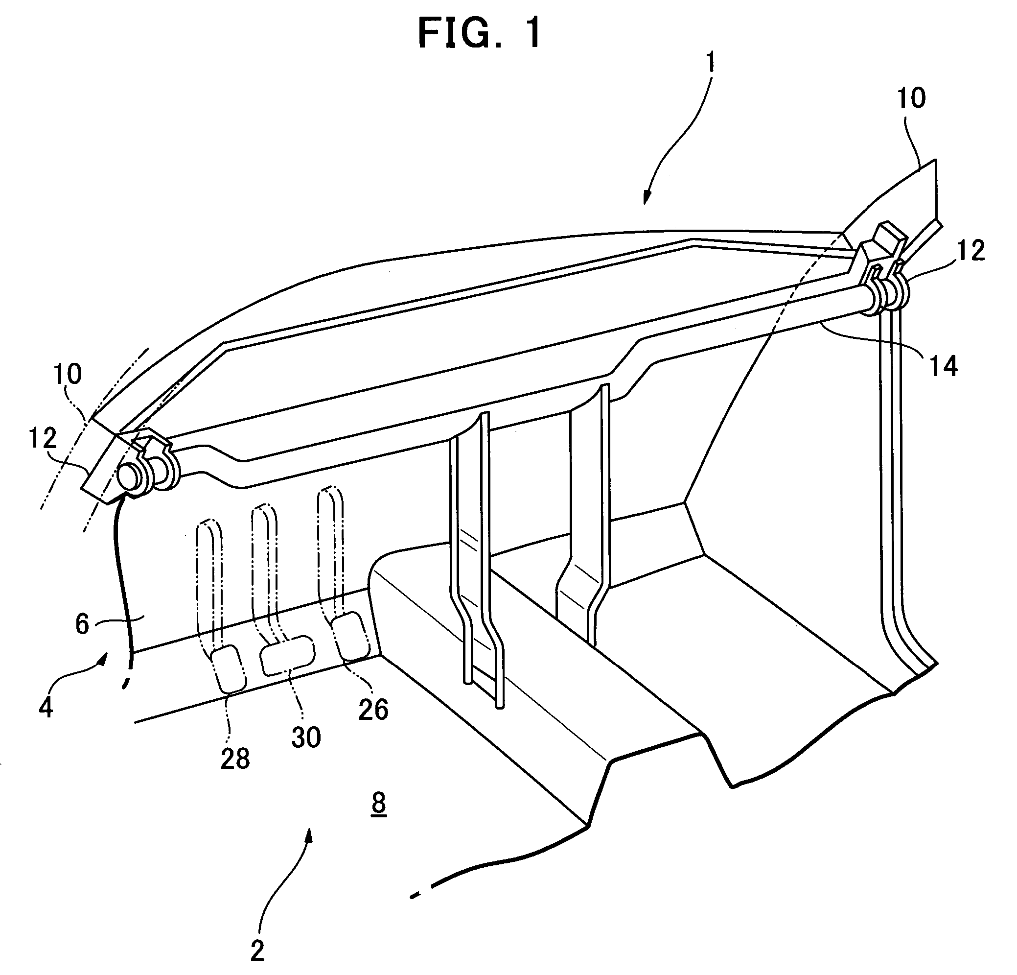
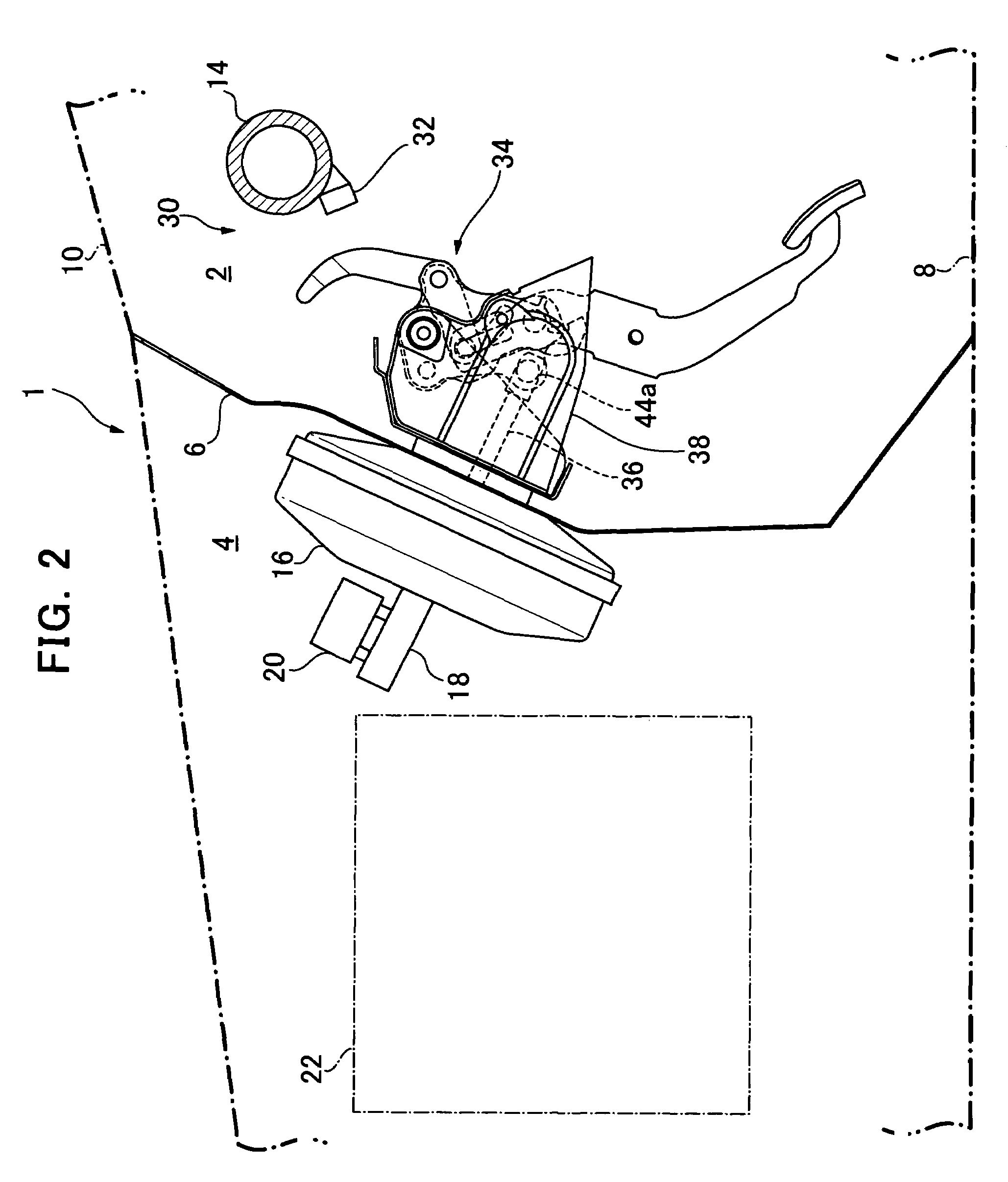
[0253]FIG. 21 is a left side view showing the support structure for a brake pedal of a vehicle of the fourth embodiment of the present invention, FIG. 22 is a cross-sectional view of the pedal unit along the line B-B shown in FIG. 21, and FIG. 23 is an exploded view of the parts of the pedal unit.

first embodiment

[0254]As shown in FIG. 21, the same as the present invention, the vehicle 1 includes a dash board lower panel 6 separating the cabin 2 of the vehicle 1 from the engine room 4, and an instrument panel member 14. A master bag 16 and a master cylinder 18 are attached to the dash board lower panel 6 on its side facing the engine room 4, and a brake pedal support structure 100 is attached to the other side facing the cabin of the vehicle.

[0255]The brake pedal support structure 100 is comprised of an integrated brake pedal unit 102 and a bracket 104 or pedal bracket. This bracket 104 is attached to the dash board lower panel 6, and the brake pedal unit 102 is pivotablly supported by a pin shaft 106 attached to this bracket 104.

[0256]Next, as can be seen in FIGS. 21 and 22, the brake pedal unit 102 includes an upper pedal member 110, a lower pedal member 112, a cam member 114, a lever member 116 or abutting member, and engaging member 118. A pedal 112a is attached at the bottom end of the ...


PUM


Abstract

A support structure for a pedal of a vehicle pivotablly supports a pedal assembly (34) to a pedal bracket (38) mounted on a vehicle dash panel (6). The support structure for a pedal of a vehicle includes a reinforce member (14) for the vehicle body; an upper pedal member (44, 46); a lower pedal member (48) having a pedal (48c) at its lower end; an abutting member (50) not coming into contact with the reinforce member when the vehicle is in a normal operation, while it abuts against the reinforce member at its abutting portion (50g) by moving in the rearward direction of the vehicle body when the vehicle crashes; and a connecting mechanism (60) for connecting the abutting member to the lower pedal member in such a manner that relative movement with respect to each other is prevented when the vehicle is in a normal operation, while the connecting mechanism forcibly displaces the lower portion (48b) of the lower pedal member, which is the part locating below the pivot shaft of the lower pedal member, in a forward direction with respect to the upper pedal member when the vehicle crashes.

Description

BACKGROUND OF THE INVENTION[0001]1. Field of the Invention[0002]The present invention relates to a support structure for a pedal of a vehicle, and in particular to a support structure for a pedal of a vehicle which pivotablly supports a pedal assembly to a pedal bracket mounted on the vehicle dash panel.[0003]2. Description of the Related Art[0004]In vehicle accidents such as front end collisions, the engine of the vehicle is forced rearwardly by a large load force affecting the front portion of the vehicle which causes the brake pedal and / or the clutch pedal attached to the dash-board lower panel to be pushed into the cabin of the vehicle, thereby interfering with the driver's feet or compressing the foot space of the driver.[0005]In order to prevent such an interference, for example, Japanese Patent Unexamined Publication No. 2001-47986(A1) discloses an escape structure for a foot pedal wherein the foot pedal is attached to a pivotable link which is pivotablly connected both to a ...

Claims


Application Information

Patent Timeline
Patent Type & Authority Patents(United States)
IPC IPC(8): G05G1/30B60R21/09B60T7/06
CPCB60R21/09Y10T74/20888Y10T74/20528
Inventor MIYOSHI, KEISUKETOMONOU, KAZUNORIMURAYAMA, TAKESHINOMURA, FUMIHIKOUTSUMI, HIROYUKIHIURA, TETSUOYAMAMOTO, KATSUHIKO
Owner AUTO TECH CORP
Why Eureka
Try Eureka