Joint for flat parts

a flat part and joint technology, applied in the direction of rod connection, sheet joining, large fixed member, etc., can solve the problems of weak bending of joints, insufficient mechanical strength of joints, and inability to join wide plates

Inactive Publication Date: 2008-08-26
KOZHUEV VITAL IVANOVICH
View PDF8 Cites 57 Cited by
  • Summary
  • Abstract
  • Description
  • Claims
  • Application Information

AI Technical Summary

Benefits of technology

[0013]The novel features of the present invention provide an important technical effect produced by the inventive joint. The connecting flat parts effectively work not only in tension but also in bending (in one direction) and in shear in the direction which is perpendicular to the surface of the connecting parts. This enables the industrial application of the invention for reliable joining of elements of various constructions, including building constructions.

Problems solved by technology

The disadvantages of said engineering solution are in that such joint allows joining only narrow planks with a lath; the joining of wide plates is practically impossible, because it is very difficult to prevent the cramping of plates when overlapping them; also the joint is weak in bending because of the stress concentration that is produced in the bending points.
Therefore, said assembly does not provide sufficient mechanical strength of the joint, because it is fundamentally unsuitable for the joining of rigid parts.
However, the solution is unsuitable when the joint works in bending or in shear in the direction which is perpendicular to the surface of the connecting parts.

Method used


Image

  • Joint for flat parts
  • Joint for flat parts
  • Joint for flat parts

Examples


Embodiment Construction

.

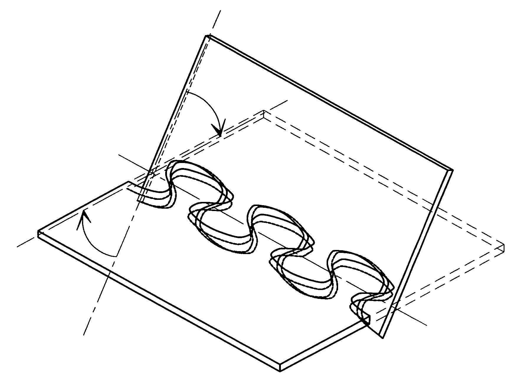
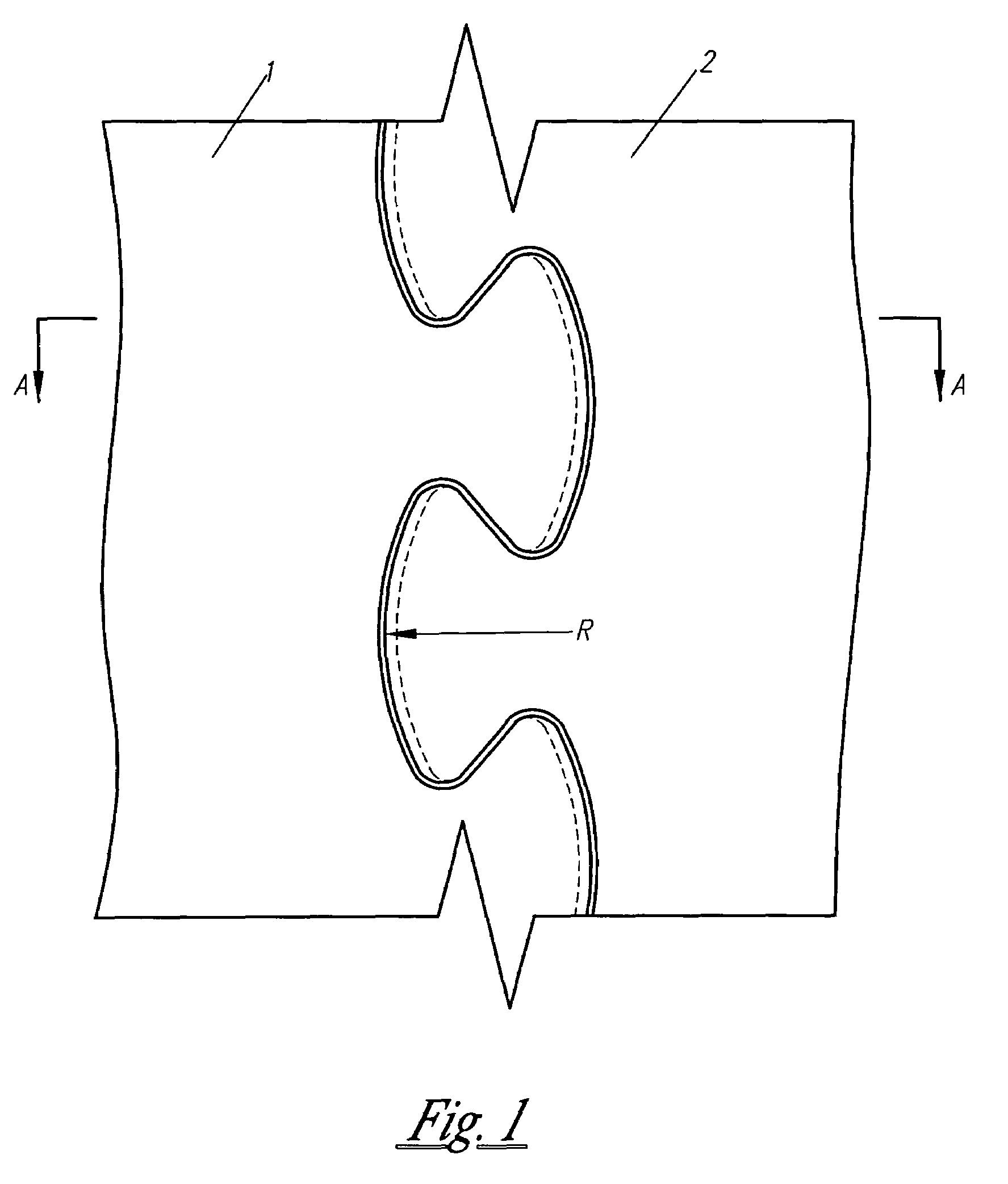
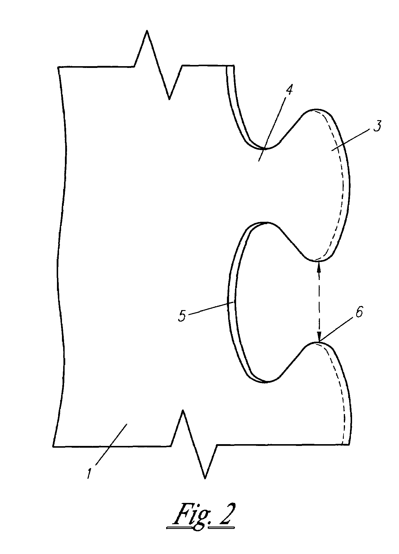
[0023]The joint for flat parts 1 and 2 comprises projections, which are embodied on the mating sides of the parts in the form of bulbous breadths 3 at the edge thereof and necks 4 at the basis thereof, and complementary joggles, which are embodied in the form of bulbous slots 5 corresponding to the bulbous breadths 3 of the projections and gradually changing into grooves 6 corresponding to the projections necks 4. The surfaces 7 of the projections edges and the surfaces 8 of the slots bottoms mating therewith are embodied in the form of cones. The guiding line 9 of the conical surface 7 passes through the peak 11, and the guiding line 10 of the conical surface 8 passes through the peak 12; the peaks 11 and 12 are arranged on the opposite sides with respect to the connecting parts.

[0024]Generally the radius of curvature R of the guiding lines of the conical surfaces 7 and 8 (the radius of curvature of the projection is equal to the radius of curvature of the slot within the accuracy...


PUM

PropertyMeasurementUnit
radius of curvatureaaaaaaaaaa
angleaaaaaaaaaa
tension-compressionaaaaaaaaaa

Abstract

A joint for flat rigid parts comprises projections, which are embodied on the mating sides of the parts in the form of bulbous breadths at the edge thereof and necks at the basis thereof, and complementary joggles, which are embodied in the form of bulbous slots corresponding to the bulbous breadths of the projections and gradually changing into grooves corresponding to the projections necks. The surfaces of the projections edges and the surfaces of the slots bottoms mating therewith are embodied in the form of cones, wherein the peaks of the conical surfaces of the projections edges and of the slats bottoms are arranged an the opposite sides with respect to the connecting parts. The radius of curvature of the guiding lines of the conical surfaces of the projections edges and of the slots bottoms can be embodied in such a way that they tend to infinity; at least one connecting part can be embodied in the form of a through-thickness composite part.

Description

BACKGROUND OF THE INVENTION.[0001]The invention relates to detachable joints for flat parts and can be used, in particular, for joining elements of building constructions, etc.BACKGROUND ART[0002]A joint of “tongue-and-groove” type is known in the art, RU, C1, 2063158. The construction is intended for joining the end surfaces of planks, which have longitudinal sides mated therebetween, with a transversal lath, wherein the joint between the planks and the joint between the planks and the lath are formed by complementary joggles and projections with shoulders, which are embodied in the form of a dovetail, and the shoulders are slanted from the surface perpendicular to the base plane of the planks towards the edges of the projection and the joggle.[0003]The disadvantages of said engineering solution are in that such joint allows joining only narrow planks with a lath; the joining of wide plates is practically impossible, because it is very difficult to prevent the cramping of plates wh...

Claims


Application Information

Patent Timeline
Patent Type & Authority Patents(United States)
IPC IPC(8): E04B1/00F16B5/00F16B5/07F16B12/22
CPCF16B5/008F16B5/07Y10T403/655Y10T403/7094Y10T403/7045Y10T403/65Y10T403/553Y10T403/7015Y10T403/581F16B2200/30F16B2200/69
Inventor KOZHUEV, VITALY IVANOVICH
Owner KOZHUEV VITAL IVANOVICH
Why Eureka
Try Eureka