Heat dissipation apparatus

a technology of heat dissipation apparatus and fan, which is applied in the direction of wind motor with parallel air flow, wind motor with perpendicular air flow, liquid fuel engine components, etc., can solve the problems of more noise, damage to electronic devices, and deterioration of electronic devices, so as to reduce noise, improve fan performance, and stabilize the airflow

Active Publication Date: 2008-08-26
DELTA ELECTRONICS INC
View PDF17 Cites 12 Cited by
  • Summary
  • Abstract
  • Description
  • Claims
  • Application Information

AI Technical Summary

Benefits of technology

[0009]Hence, the invention provides a heat dissipation apparatus (a fan) and a fan frame thereof. The fan and fan frame have a smooth curved expansion portion capable of reducing noise generated by friction between airflow and the inner peripheral wall of a passage, stabilizing and concentrating the airflow, and enhancing performance of the fan. Moreover, the inner peripheral wall of the fan frame outwardly extends, increasing areas of air intake or discharge, concentrating the airflow, and enhancing performance of the fan. Further, the fan is easily applied to a heat dissipation system or any other electronic devices which generate heat by assembling without modifying arrangement of the system.

Problems solved by technology

If heat generated by an electronic device is not efficiently dissipated, performance of the electronic device may deteriorate or the electronic device may be damaged.
Specifically, the higher the rotational speed of the fan, the more the noise generated thereby.

Method used


Image

  • Heat dissipation apparatus
  • Heat dissipation apparatus
  • Heat dissipation apparatus

Examples


Embodiment Construction

[0039]The following description is of the best-contemplated mode of carrying out the invention. This description is made for the purpose of illustrating the general principles of the invention and should not be taken in a limiting sense. The scope of the invention is best determined by reference to the appended claims.

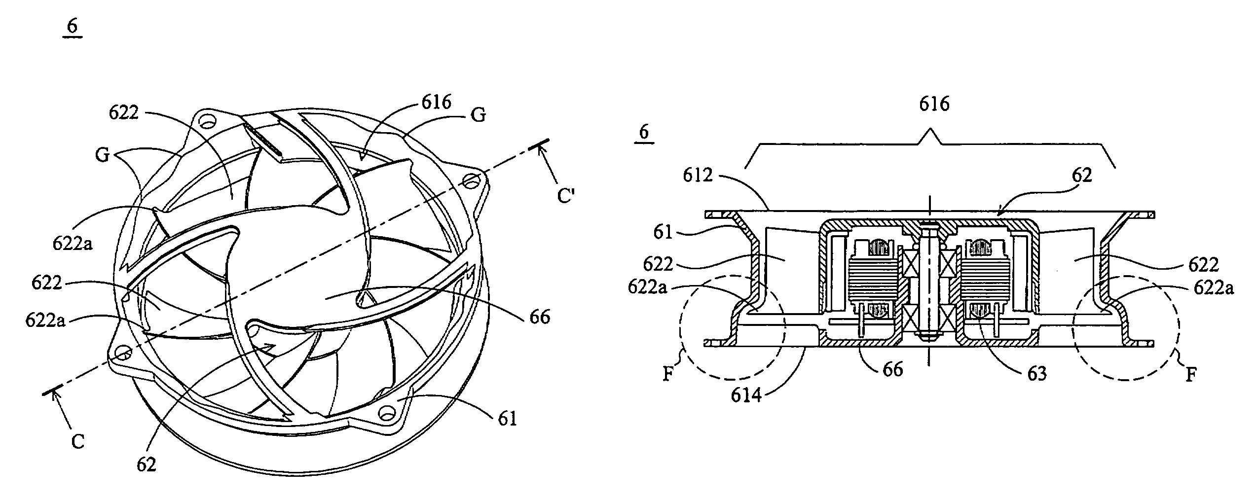
[0040]Referring both to FIG. 2A and FIG. 2B, the heat dissipation apparatus 2 can be, for example, an axial flow fan and has a fan frame 21, an impeller 22, and a motor base 26. The fan frame 21 may be a substantially rectangular, circular, elliptical, or rhomboid casing. The fan frame 21 has a through hole so as to form a passage 216 therein, an air inlet 212, and an air outlet 214. The air inlet 212 is connected to the air outlet 214 by way of the passage 216. The passage 216 can guide airflow from one opening (air inlet 212) to the other opening (air outlet 214). Airflow generated by the impeller 22 can thus enter and leave the fan frame 21. Additionally, multiple t...


PUM


Abstract

A heat dissipation apparatus. A fan frame includes an air inlet, an air outlet, a passage, and a curved expansion portion. The air inlet is opposite the air outlet. The passage is between the air inlet and the air outlet, guiding airflow from the air inlet to the air outlet. The curved expansion portion is radially and outwardly extended from an inner peripheral wall of the passage at the air inlet or air outlet. An impeller is disposed in the fan frame and includes a plurality of blades. Each blade is disposed in the passage and includes an extension end extending to the curved expansion portion.

Description

CROSS REFERENCE TO RELATED APPLICATIONS[0001]This application is a Continuation-In-Part of U.S. patent application Ser. No. 11 / 230,450, filed Sep. 21, 2005 and entitled “HEAT DISSIPATION APPARATUS AND FAN FRAME THEREOF”, which is now abandoned, for which priority is claimed under 35 U.S.C. § 129.BACKGROUND OF THE INVENTION[0002]1. Field of the Invention[0003]The invention relates to a heat dissipation apparatus, and more particularly to a heat dissipation apparatus providing reduced noise.[0004]2. Description of the Related Art[0005]As performance of electronic devices is promoted, heat dissipation apparatuses or systems are indispensable and thus used in the electronic devices. If heat generated by an electronic device is not efficiently dissipated, performance of the electronic device may deteriorate or the electronic device may be damaged.[0006]Fans serve widely as heat dissipation apparatuses. FIG. 1A is a schematic view of a conventional fan 1, and FIG. 1B is a schematic cross ...

Claims


Application Information

Patent Timeline
Patent Type & Authority Patents(United States)
IPC IPC(8): F04D29/54
CPCF04D25/0613F04D29/545F04D29/526
Inventor HO, SHIH-HUACHEN, HAO-MINGLEI, TSUNG-YUHUANG, WEN-SHI
Owner DELTA ELECTRONICS INC
Why Eureka
Try Eureka