Random engagement roller chain sprocket and timing chain system including same

a timing chain and roller chain technology, applied in the direction of gearing, gearing details, hoisting equipment, etc., can solve the problems of noise in the roller chain drive system, several components of the chain drive system being undesirable,

Inactive Publication Date: 2008-08-26
HH CLOYES INC
View PDF104 Cites 64 Cited by
  • Summary
  • Abstract
  • Description
  • Claims
  • Application Information

AI Technical Summary

Benefits of technology

[0022]In accordance with another aspect of the present development, a roller chain sprocket is adapted to mesh with an associated roller chain having rollers defining a minimum roller radius. The roller chain sprocket comprises a first plurality of A-profile teeth formed with a first asymmetric profile and a second plurality of B-profile teeth formed with a second asymmetric profile that is different from the first asymmetric profile. The A-profile teeth each define a first pressure angle and the B-profile teeth each define a second pressure angle that is at least 5 degrees greater than the first pressure angle. A root surface is located between successive teeth of the sprocket. The root surface is defined by a radius that is smaller than the minimum roller radius to prevent contact between said rollers and said root surface.

Problems solved by technology

Chain drive systems have several components of undesirable noise.
A major source of roller chain drive noise is the sound generated as a roller leaves the span and collides with the sprocket during meshing.

Method used


Image

  • Random engagement roller chain sprocket and timing chain system including same
  • Random engagement roller chain sprocket and timing chain system including same
  • Random engagement roller chain sprocket and timing chain system including same

Examples


Embodiment Construction

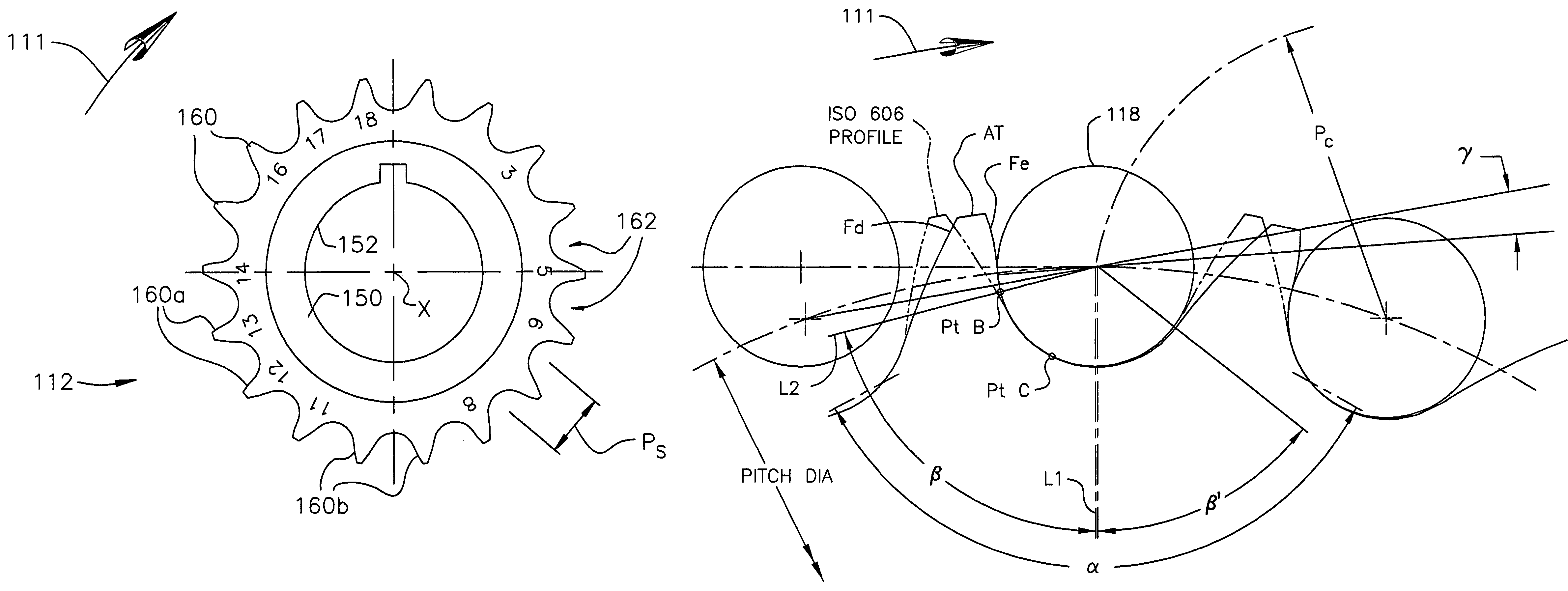
[0037]FIG. 3 illustrates a roller chain drive system 110 such as an automotive timing system formed in accordance with the present invention. The chain drive system includes a drive sprocket 112 and a driven sprocket 114. The system further includes a roller chain 116 having rollers 118 which engage and wrap about sprockets 112,114. The roller chain 116 is drivingly engaged with the sprockets 112,114, both of which rotate in a clockwise direction as shown by arrow 111. At least one of the sprockets 112,114 is formed in accordance with the present invention.

[0038]The roller chain 116 has two spans extending between the sprockets 112,114; a slack strand 120 and taut strand 122. In the illustrated example, the sprocket 112 is a drive sprocket and the sprocket 114 is driven by the sprocket 112 via chain 116. As such, the roller chain 116 is under tension as shown by arrows 124. A central portion of the taut strand 122 is guided from the driven sprocket 114 to the drive sprocket 112 with...


PUM


Abstract

A sprocket and a roller chain drive system including same are disclosed. The sprocket is a random engagement sprocket comprising a first plurality of A-profile teeth formed with a first asymmetric profile and a second plurality of B-profile teeth formed with a second asymmetric profile. The A-profile teeth each define a first pressure angle and the B-profile teeth each define a second pressure angle that is at least 5 degrees greater than said first pressure angle so that a minimum separation Δ is defined. The sprocket is defined with added chordal pitch reduction of 0.2% up to 1% relative to the link pitch of the associated roller chain. The sprocket can be defined with root relief and/or can comprise resilient cushion rings. Initial roller contacts made with the A-profile and B-profile teeth are modulated owing to the pressure angle separation and added chordal pitch reduction.

Description

CROSS-REFERENCE TO RELATED APPLICATIONS[0001]This application is a continuation-in-part of U.S. application Ser. No. 10 / 004,544 filed Dec. 4, 2001, now U.S. Pat. No. 6,761,657 which is a continuation-in-part of U.S. application Ser. No. 09 / 321,246 filed May 27, 1999, now U.S. Pat. No. 6,325,734, which is a continuation of U.S. application Ser. No. 08 / 992,306 filed Dec. 17, 1997, now U.S. Pat. No. 5,921,879, which claims benefit of the filing date of U.S. provisional application Ser. No. 60 / 032,379 filed Dec. 19, 1996, and all of said applications are hereby incorporated herein by reference. This application is also a continuation-in-part of U.S. application Ser. No. 10 / 123,940 filed Apr. 16, 2002, now U.S. Pat. No. 7,074,147 which is a continuation-in-part of U.S. application Ser. No. 09 / 728,698 filed Dec. 1, 2000, now U.S. Pat. No. 6,371,875, which is a continuation of U.S. application Ser. No. 09 / 383,128 filed Aug. 25, 1999, now U.S. Pat. No. 6,179,741, which claims benefit of the...

Claims


Application Information

Patent Timeline
Patent Type & Authority Patents(United States)
IPC IPC(8): F16H7/06F16G1/28F16H55/30F16H57/00
CPCF16H7/06F16H55/30F16H57/0006F16H2055/086
Inventor YOUNG, JAMES D.MARSHEK, KURT M.
Owner HH CLOYES INC
Why Eureka
Try Eureka