Multipolar, multi-lumen, virtual-electrode catheter with at least one surface electrode and method for ablation

a virtual electrode and electrode technology, applied in the field of virtual electrode electrode catheters, can solve the problems of increasing the depth of the lesion, requiring high power, and increasing the temperature at the electrode-tissue interface, so as to improve the efficiency of ablation

Inactive Publication Date: 2008-08-26
ST JUDE MEDICAL ATRIAL FIBRILLATION DIV
View PDF51 Cites 179 Cited by
  • Summary
  • Abstract
  • Description
  • Claims
  • Application Information

AI Technical Summary

Problems solved by technology

Increased lesion depth, therefore, requires high power.
High power, however, causes rapid temperature increases and potential “hot-spots” at the electrode-tissue interface.
Existing techniques can be, therefore, highly inefficient.

Method used


Image

  • Multipolar, multi-lumen, virtual-electrode catheter with at least one surface electrode and method for ablation
  • Multipolar, multi-lumen, virtual-electrode catheter with at least one surface electrode and method for ablation
  • Multipolar, multi-lumen, virtual-electrode catheter with at least one surface electrode and method for ablation

Examples


first embodiment

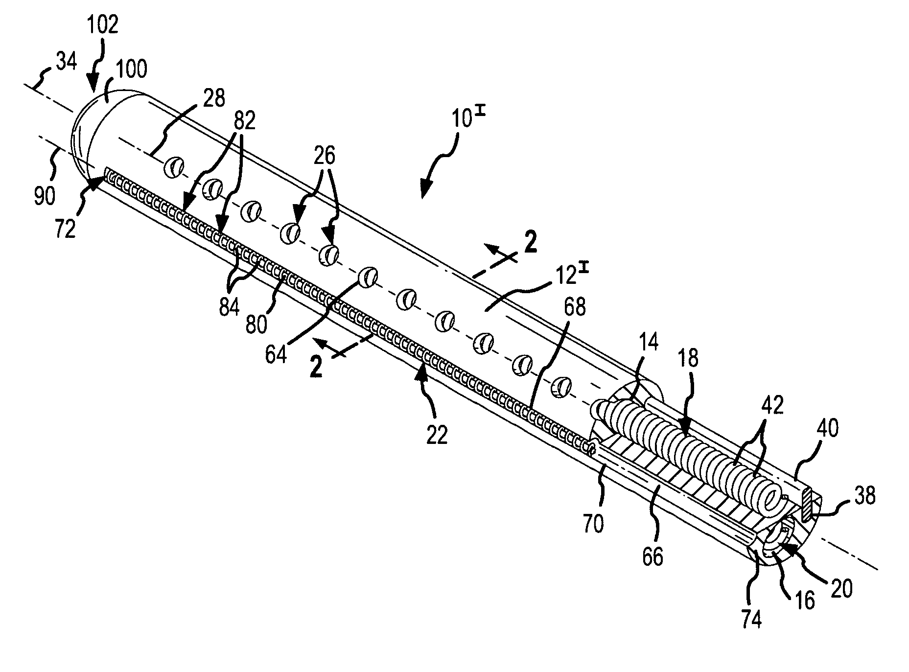
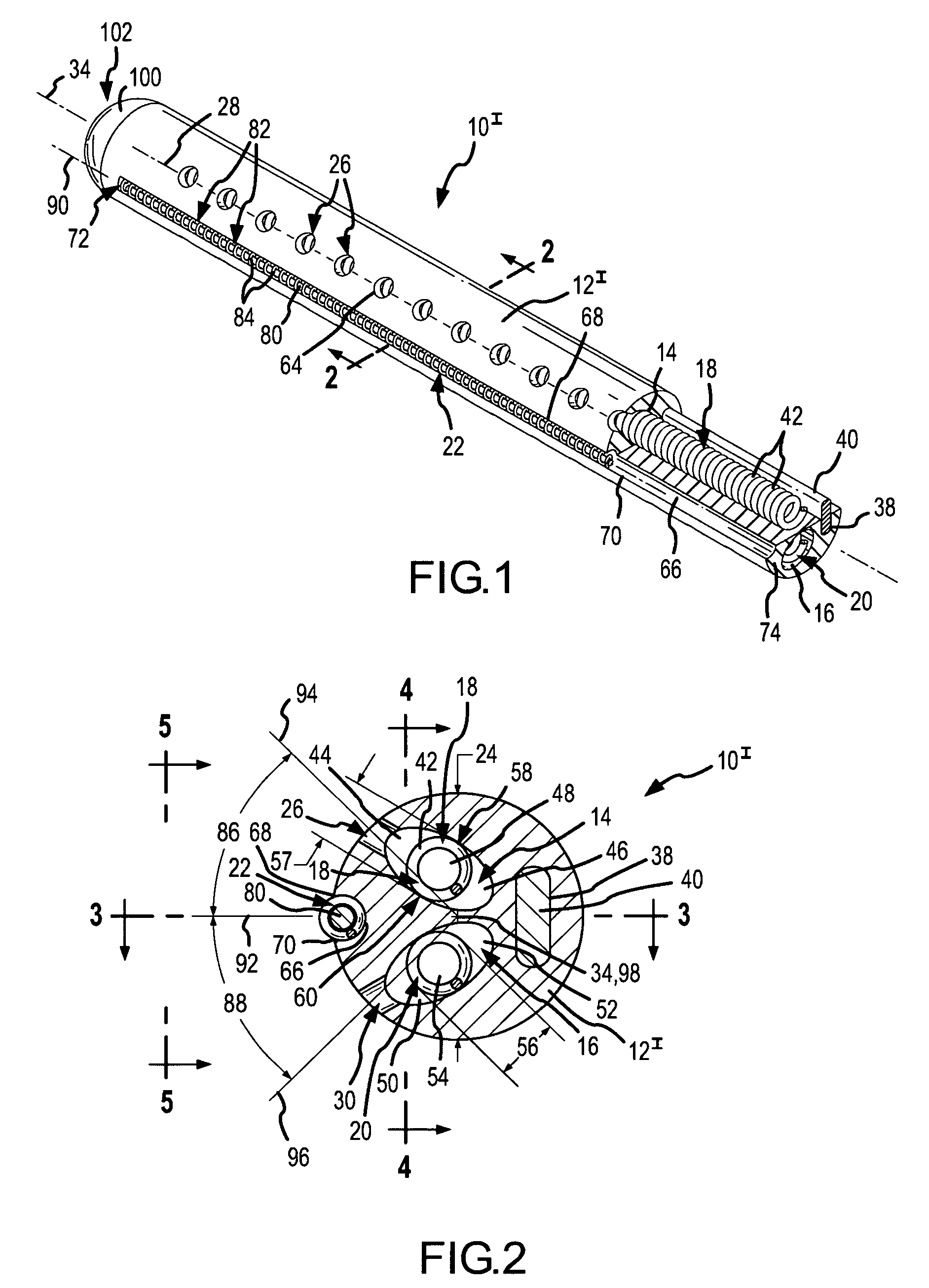
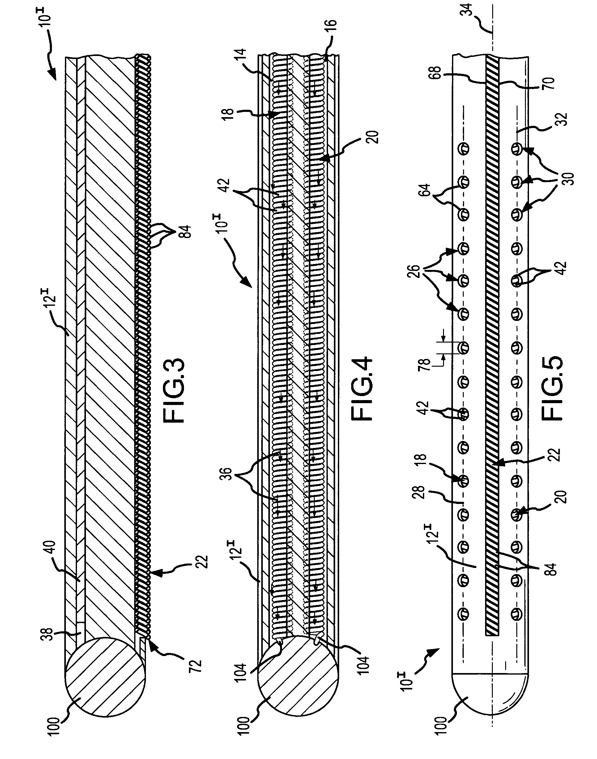
[0043]As shown in FIGS. 1, 2, and 5, an exit feature extends through a sidewall of the catheter body. In particular, the exit feature in this first embodiment comprises a first plurality of exit portholes or nozzles 26 that are arranged along a first longitudinally-extending porthole centerline 28 along the surface of the catheter body 12I, and a second plurality of exit portholes or nozzles 30 that are arranged along a second longitudinally-extending porthole centerline 32 along the surface of the catheter body. As best seen by looking at FIGS. 2 and 5, these exit portholes 26, 30 extend through the sidewall of the catheter body 12I. In the depicted embodiment, as shown to good advantage in FIG. 2, the exit portholes 26, 30 extend radially through the sidewall relative to a catheter longitudinal axis 34.

[0044]The catheter body 12I includes at least two longitudinally-extending internal lumen 14, 16, and an internal flexible current carrier or conductor 18, 20 is mounted in each int...

second embodiment

[0061]FIGS. 6 and 7 depict views of a distal portion 10II, of a multipolar, multi-lumen virtual-electrode catheter according to the present invention. This second embodiment is similar to the first embodiment. The exit feature, however, comprises a first exit slot 106 that extends longitudinally along a first longitudinally-extending slot centerline 108 and through an external wall of the catheter body 12II and into the first elliptical internal lumen 14; and a second exit slot 110 that extends longitudinally along a second longitudinally-extending slot centerline 112 and through an external wall of the catheter body 12II and into the second elliptical internal lumen 16. The two slots 106, 110 replace the two rows of exit portholes 26, 30 of the first embodiment. The slot width 114 of each slot may be, for example, 0.007 inches (i.e., approximately 0.18 mm). In this second embodiment, a single large internal coil 18, 20 is again present in each internal lumen 14, 16, and the surface...

sixth embodiment

[0071]As suggested by FIG. 14, which is a cross-sectional view of the distal portion 10VI of a multipolar, multi-lumen virtual-electrode catheter taken along line 14-14 of FIG. 13, this embodiment may use two fluid sources (not shown). For example, a first fluid source may supply cooling fluid 132 to the surface electrode tube 128, and a second fluid source may provide conductive fluid 36 (see e.g., FIG. 4) to the elliptical internal lumens 14, 16 in which the large internal coils 18, 20 depicted in FIGS. 13 and 14 reside. The exit port 134 shown in FIG. 14 may be somewhat constricted to control the rate of flow through the surface electrode tube 120. Since it is possible that the ablative energy (e.g., RF energy) being delivered to the conductive fluid 36 that ultimately departs the exit slots 106, 110 may reach the fluid 132 flowing through the exit port 134 of the surface electrode tube 128, having two separate fluid supply systems is desirable. In order to control the total amo...


PUM


Abstract

Multipolar, multi-lumen, virtual-electrode catheters having at least one surface electrode, and methods for treatment (e.g., treatment of cardiac arrhythmias) with such catheters are disclosed. The catheters have at least two internal lumens, and at least one internal, flexible electrode rides in each internal lumen. The flexible electrodes carry treatment energy (e.g., radiofrequency energy). The energy exits the catheters via at least one exit feature (e.g., slots, portholes, or micro-pores). The methods for treatment include operating the catheters in different modes depending upon location and type of treatment to be performed. The treatment energy delivered by one of the internal, flexible electrodes may be directed to the other internal, flexible electrode; or the energy delivered by one or both of the internal, flexible electrodes may be directed to one or more surface electrodes. The delivered energy establishes at least one electric field, and possibly one or more lesions, in the tissue.

Description

BACKGROUND OF THE INVENTION[0001]a. Field of the Invention[0002]The instant invention is directed toward virtual-electrode catheters and to methods for using such virtual-electrode catheters. More specifically, it relates to multipolar, multi-lumen virtual-electrode catheters having at least two internal electrodes and at least one surface electrode, and to methods of using these catheters for treatment of cardiac arrhythmias via, for example, radiofrequency (RF) ablation.[0003]b. Background Art[0004]Conventional catheter techniques of RF ablation for treating cardiac arrhythmias use RF electrodes in a unipolar mode. In this mode, only the active RF electrodes are placed at the site of the ablation. The dispersive electrodes are placed at locations remote from the ablation site, typically on the skin of the patient.[0005]In the unipolar mode, the RF current decreases as 1 / r2, and the RF energy decreases as 1 / r4, where “r” is the radial distance from an active electrode of a catheter...

Claims


Application Information

Patent Timeline
Patent Type & Authority Patents(United States)
IPC IPC(8): A61B18/18
CPCA61B18/1492A61B2218/002A61B2018/1472A61B2018/1467
Inventor PAUL, SAURAVBELHE, KEDAR RAVINDRA
Owner ST JUDE MEDICAL ATRIAL FIBRILLATION DIV
Why Eureka
Try Eureka