
System and method for triggering an explosive device

a technology of explosive devices and systems, applied in the field of radar detection systems, can solve the problems of small rf power in the band, smoke, black targets, and limited conventional radio frequency and radar approaches, and achieve the effects of reducing the risk of explosion, and reducing the detection accuracy

Inactive Publication Date: 2008-08-26
CEDAR RIDGE RES
View PDF32 Cites 13 Cited by
  • Summary
  • Abstract
  • Description
  • Claims
  • Application Information

AI Technical Summary

Benefits of technology

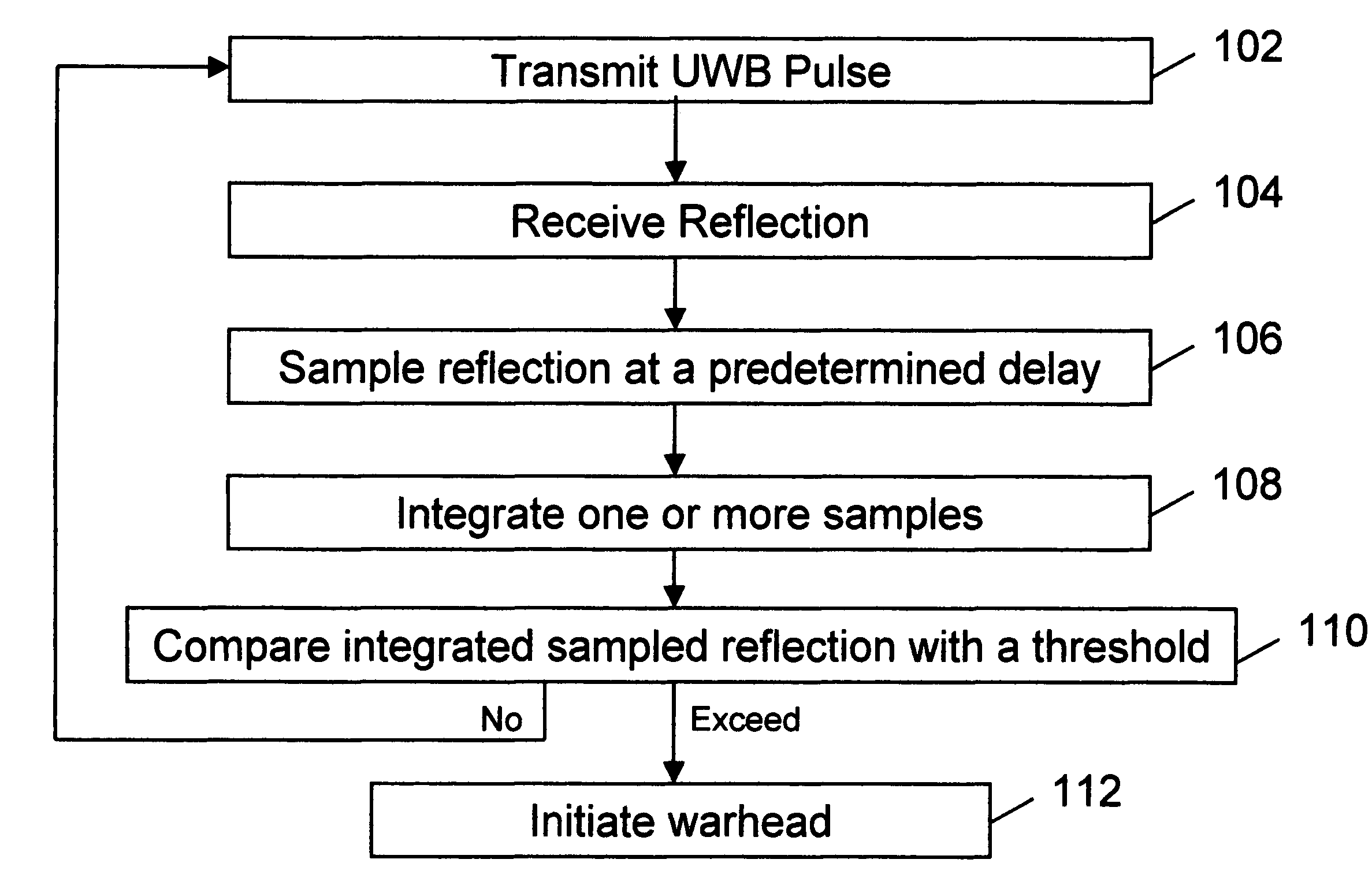
"The present invention is a proximity fuze that uses ultra wideband (UWB) radar to detect and identify targets. The fuze includes an antenna with a conical radiation pattern and a timing system. The invention also utilizes multiple range shells to further discriminate target characteristics including velocity. The system can trigger detonation based on target range, velocity, signal amplitude, and radar signal phase. The invention has a long storage life and is powered by a turbine generator and internal gas source. The technical effects of the invention include improved target detection and improved safety in the use of proximity fuze systems."

Problems solved by technology

Optical techniques have issues with rain, smoke, and black targets and the like.
Conventional radio frequency and radar approaches are limited, however, for close range triggering in clutter environments because of difficulty achieving clutter rejection.
Also, narrow band techniques are easily jammed by a small amount of RF power in band.
Small missiles present an especially challenging set of systems requirements.
Conventional RF techniques lack the resolution to achieve required performance in these complex engagements, especially in a very small package consuming a small amount of power.
Small missiles are manufactured in large quantity and stored for twenty or more years where it is impractical to provide periodic maintenance including battery replacement.

Method used


Image

  • System and method for triggering an explosive device
  • System and method for triggering an explosive device
  • System and method for triggering an explosive device

Examples


Embodiment Construction

[0039]The present invention will now be described more fully in detail with reference to the accompanying drawings, in which the preferred embodiments of the invention are shown. This invention should not, however, be construed as limited to the embodiments set forth herein; rather, they are provided so that this disclosure will be thorough and complete and will fully convey the scope of the invention to those skilled in art.

UWB Background

[0040]Impulse radio has been described in a first series of patents, including U.S. Pat. No. 4,641,317 (issued Feb. 3, 1987), U.S. Pat. No. 4,743,906 (issued May 10, 1988), U.S. Pat. No. 4,813,057 (issued Mar. 14, 1989), U.S. Pat. No. 4,979,186 (issued Dec. 18, 1990), and U.S. Pat. No. 5,363,108 (issued Nov. 8, 1994) to Larry W. Fullerton. A second series of impulse radio patents includes U.S. Pat. No. 5,677,927 (issued Oct. 14, 1997), U.S. Pat. No. 5,687,169 (issued Nov. 11, 1997), U.S. Pat. No. 5,764,696 (issued Jun. 9, 1998), U.S. Pat. No. 5,832...


PUM


Abstract

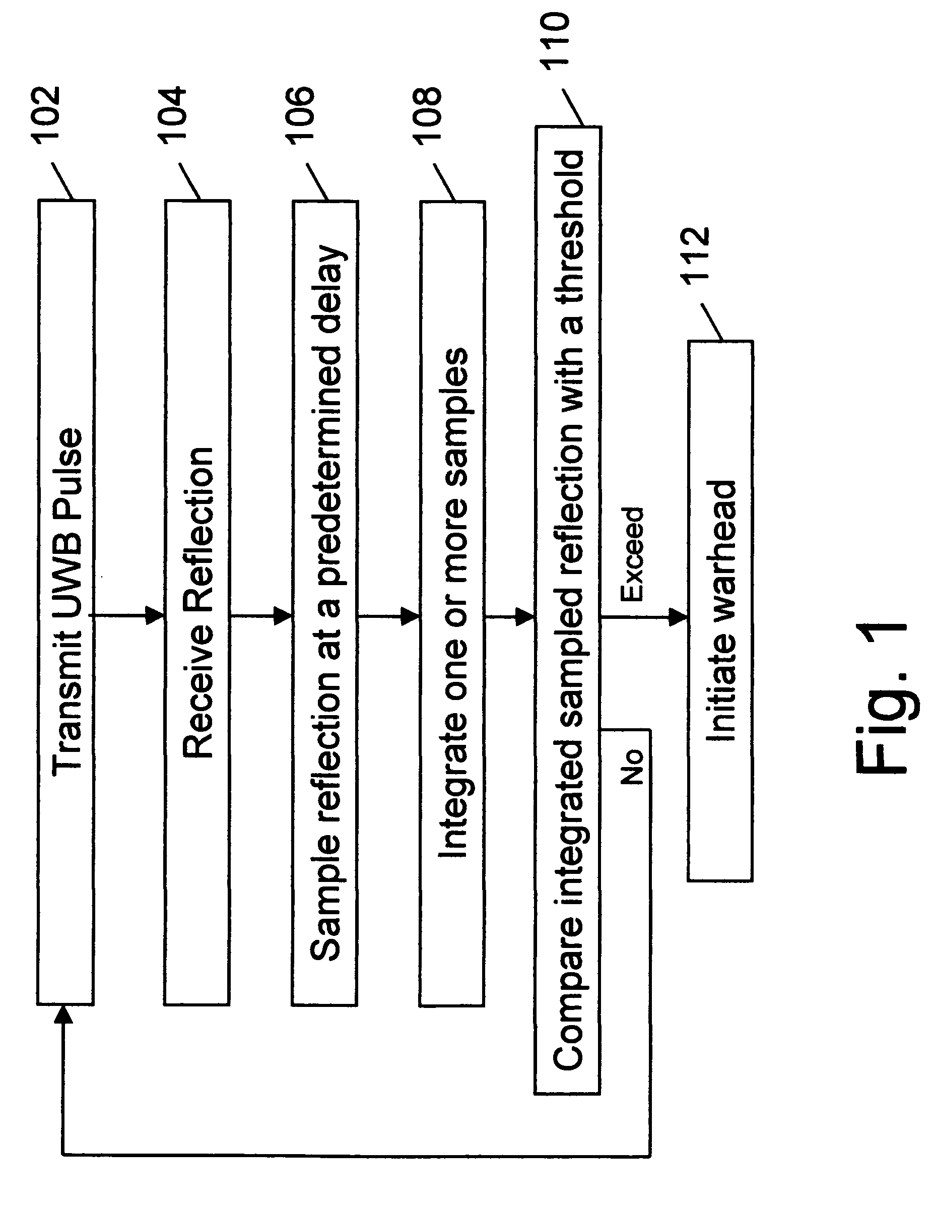
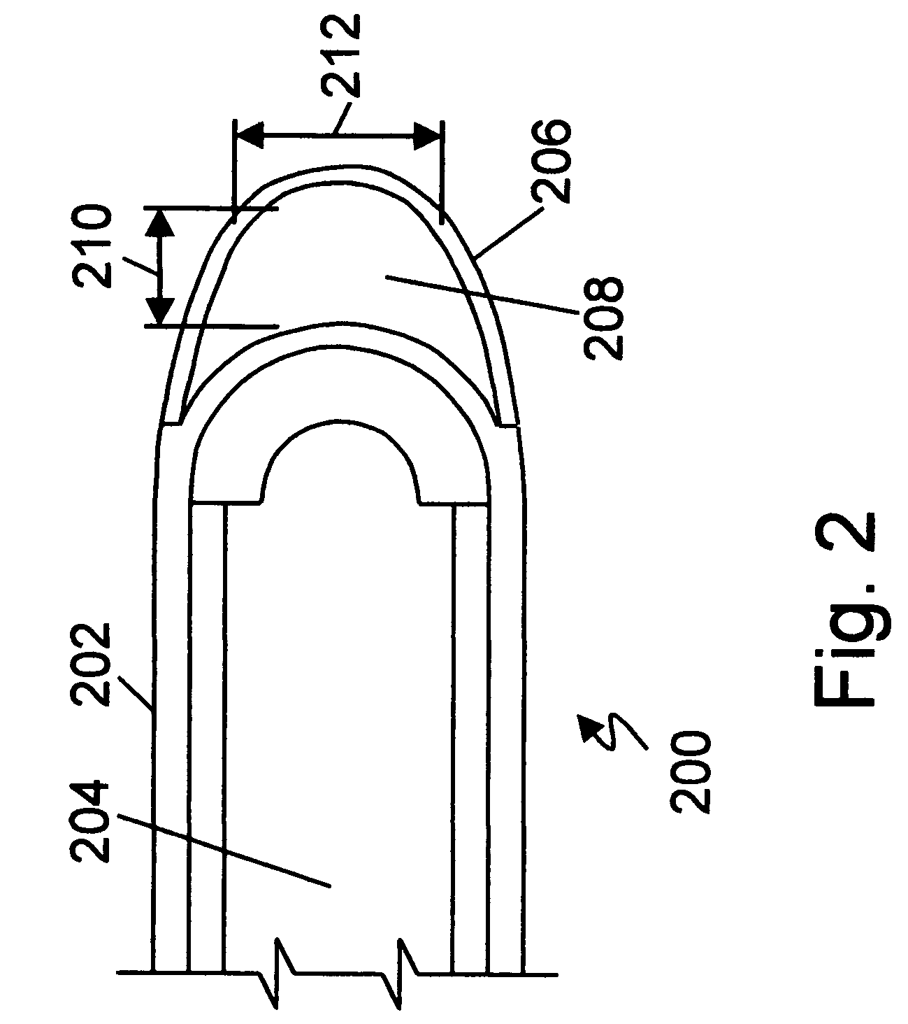
A proximity fuze (proximity fuse) comprising an ultra wideband (UWB) radar transmitter, a UWB radar receiver, an antenna, a timing system, and a signal processor. One embodiment includes an antenna with an annular conical radiation pattern. In another embodiment, a trigger delay is produced that is related to target detection range. In a further embodiment, multiple range shells are utilized to further discriminate target characteristics including velocity. A method is disclosed that utilizes target range, velocity, signal amplitude, and radar signal phase to identify the target and trigger the detonation. A proximity fuze system having a long storage life is disclosed comprising a proximity fuze element powered by a turbine generator and internal gas source.

Description

BACKGROUND[0001]1. Field of the Invention[0002]The present invention pertains to the field of radar detection systems, more particularly to the field of radio wave based proximity fuzes including logic means. 342 / 68 or 102 / 215[0003]2. Background of the Invention[0004]A proximity fuze is an explosive ignition device used in bombs, artillery shells, and mines. The fuze senses when a target is close enough to be optimally damaged or destroyed by the weapon's warhead.[0005]An example mission for a helicopter fired missile which includes a proximity fuze is to engage a small team of terrorists who possess a Short Range Air Defense (SHORAD) weapon (e.g. Red Eye, Stinger or SA-7) and intend to shoot down a commercial airliner. The missile is first aimed and then fired from the helicopter. Upon firing, the proximity fuze circuit is powered and enabled (armed). The missile may be guided or unguided during flight. Upon detecting signals indicating a proximal target, the fuze detonates the mis...

Claims


Application Information

Patent Timeline
Patent Type & Authority Patents(United States)
IPC IPC(8): F42C13/00G01S13/00
CPCF42C11/008G01S13/0209F42C13/042
Inventor TROUTMAN, DENNIS L.FLUHLER, HERBERT U.FULLERTON, LARRY W.FITZPATRICK, DOUGLAS D.RICHARDS, JAMES
Owner CEDAR RIDGE RES
Learn More