Multiple ranging apparatus

a multi-range, multi-stage technology, applied in the direction of distance measurement, instruments, focusing aids, etc., can solve the problems of inability to identify, take a considerable length of time to carry out the ranging, and the conventional multi-range apparatus has such a disadvantage, so as to achieve the effect of efficient condensation

Inactive Publication Date: 2008-08-26
SHARP KK
View PDF18 Cites 58 Cited by
  • Summary
  • Abstract
  • Description
  • Claims
  • Application Information

AI Technical Summary

Benefits of technology

[0017]According to the embodiment, the multi-wavelength light rays can separately be emitted by a simple configuration where only the plurality of light emitting elements are provided which respectively have the emission wavelengths different from one another.
[0044]According to the embodiment, light can efficiently be condensed on the light receiving section because the light can be condensed from a wider beam area in comparison with general convex lenses or the like.

Problems solved by technology

The conventional multiple ranging apparatus, however, has such a disadvantage as follows.
In this case, when distance measuring for multiple points is simultaneously carried out, it is impossible to identify which light emitting element 1 the light is emitted from, and therefore, to measure distances to two or more points.
Thus, it takes a considerable length of time to carry out the ranging.

Method used


Image

  • Multiple ranging apparatus
  • Multiple ranging apparatus
  • Multiple ranging apparatus

Examples


first embodiment

[0066]FIG. 1 is a perspective plan view showing a schematic configuration of a multiple ranging apparatus of the embodiment. FIG. 2 is a sectional view taken along a line A-A′ of FIG. 1. FIG. 3 is a sectional view taken along a line B-B′ of FIG. 1. As shown in FIG. 3, the multiple ranging apparatus 11 has a light emitting section 12 which is capable of radiating a plurality of light rays 13 having a plurality of wavelengths. The plurality of light rays 13 radiated from the light emitting section 12 are passed through and condensed by a lens 14 and then are struck on and scattered by an object (not shown). Part of the scattered rays are condensed by a light receiving lens 15 onto a light receiving section 16, and the light rays having the plurality of wavelengths are separately received by the light receiving section 16. Reference numeral 17 denotes a frame which is formed on a substrate 18 and on which the light emitting section 12 and the light receiving section 16 are placed. Nume...

first example

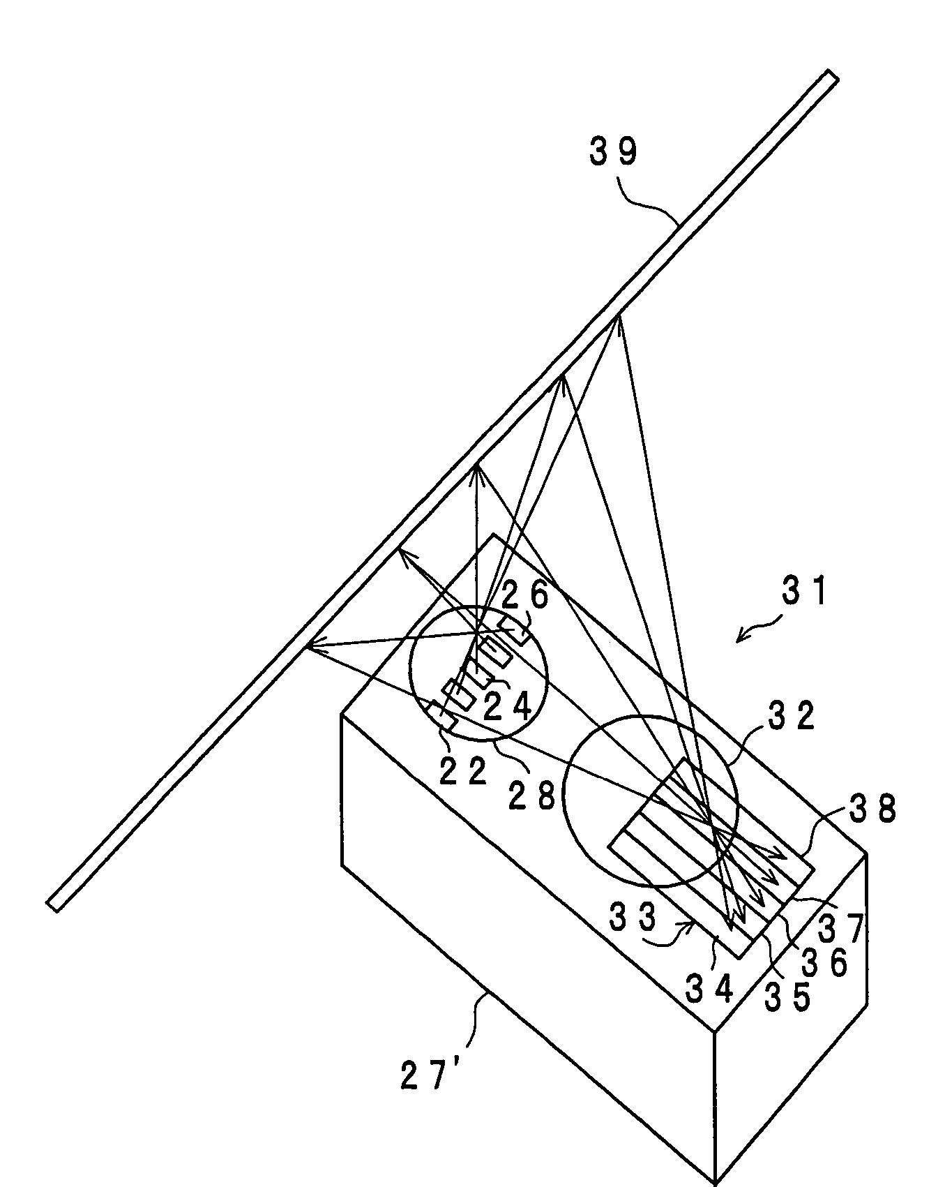
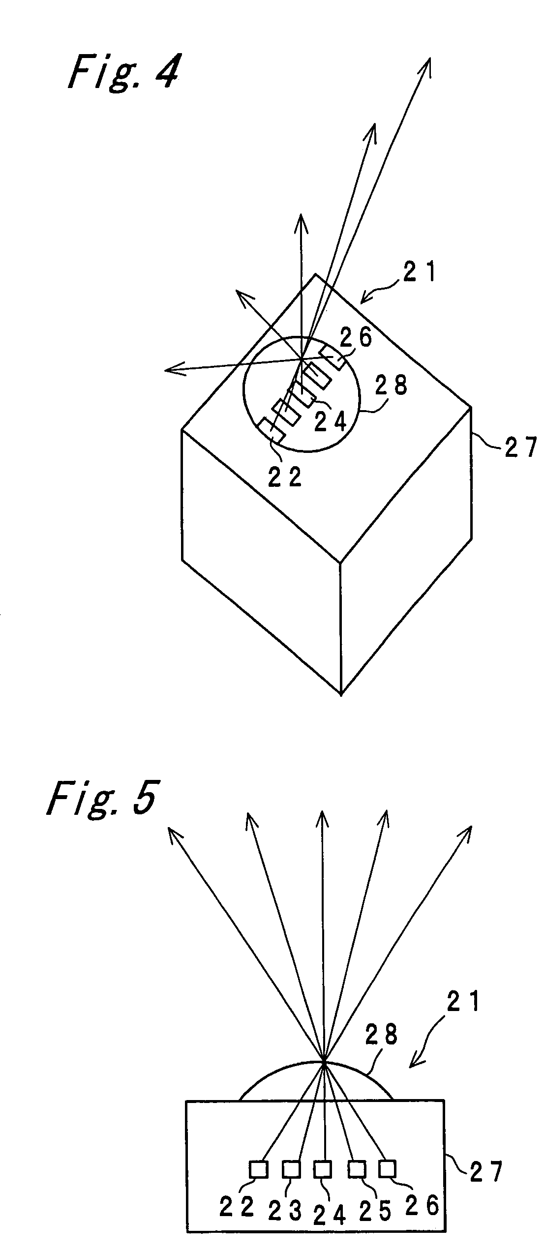
[0068]FIGS. 4 and 5 are a perspective view and a vertical sectional view, respectively, of a light emitting device 21 having the wavelength multiplying unit. The light emitting device 21 actually has a structure in which the light emitting section placed on the frame formed on the substrate is sealed with transparent resin, as shown in FIGS. 1 and 2. However, for simplification (ditto for second and third examples below), the light emitting section in FIGS. 4 and 5 is represented as one which is simply sealed with transparent resin.

[0069]In the light emitting device 21, five LEDs 22-26 are arranged in a row and are sealed with transparent resin 27. A lens 28 is formed on a top surface of the transparent resin 27 which is located over the LEDs 22-26. Wavelengths of light rays radiated from the LEDs 22-26 differ from one another. Chief rays from the LEDs 22-26 are on extension of lines connecting a center of the lens 28 and light emission positions of the LEDs 22-26. In the example, t...

second example

[0080]FIGS. 8 and 9 show a configuration of a light emitting device 41 in this example. In the light emitting device 41, five LEDs 42-46 are arranged in a row and are sealed with transparent resin 47. A lens 48 is formed on a top surface of the transparent resin 47 located over the LEDs 42-46. Light rays radiated from the LEDs 42-46 have the same wavelength. Chief rays from the LEDs 42-46 are on extension of lines connecting a center of the lens 48 and light emission positions of the LEDs 42-46. The lens 48 is arranged so that a principal axis thereof is superimposed on a chief ray from the LED 44 positioned at center.

[0081]At positions through which the chief rays extending from the LEDs 42-46 to the lens 48, optical filters 49-53 are provided which permit only light rays having specific wavelengths different from one another to pass through. Therefore, the light rays of the same wavelength emitted from the LEDs 42-46 are subjected to wavelength selection by the optical filters 49-...


PUM


Abstract

A multiple ranging apparatus has a light emitting section constituted by a plurality of aligned LEDs which emit light rays of wavelengths different from one another, and a light receiving section constituted by a plurality of aligned PSD parts which have wavelength sensitivities corresponding to the different wavelengths of the light rays emitted from the LEDs. Thus, even when ranging of respective points is simultaneously measured in multiple ranging measurement, it is possible to identify which LED the light is emitted from, and therefore, to simultaneously measure the distances of two or more points.

Description

CROSS-REFERENCE TO RELATED APPLICATIONS[0001]This nonprovisional application claims priority under 35 U.S.C. §119(a) on Patent Application No. 2004-049458 filed in Japan on Feb. 25, 2004, the entire contents of which are incorporated herein by reference.BACKGROUND OF THE INVENTION[0002]The present invention relates to a multiple ranging apparatus for detecting presence or absence of an object, a direction of the object, a distance to the object or the like at multiple points.[0003]Conventionally, for this type of apparatus, there is a multiple ranging apparatus of an automatic focusing camera as shown in FIG. 19 (see JP 07-104477 B, for example). In FIG. 19, light emitted from a light emitting element 1, which is composed of e.g. a light emitting diode (LED) or a laser diode, is made into a beam for projection by an optical lens 2. When an object exists in a detectable range, the light is reflected at a point O1 (or a point O2) on a surface of the object 3 (or the object 4) located ...

Claims


Application Information

Patent Timeline
Patent Type & Authority Patents(United States)
IPC IPC(8): G01C3/08G01B11/00G01C3/00G01C3/06G01S17/48G01S17/87G02B7/30G03B13/36H01L25/16H01L29/221
CPCG01S17/48G01S17/87H01L31/0203H01L31/173G01S7/4814H01L25/167H01L2924/0002H01L2924/00
Inventor NAGASAKA, KOHJINARASAKO, SEIICHI
Owner SHARP KK
Why Eureka
Try Eureka