Device and method for wavefront measurement of an optical imaging system by means of phase-shifting interferometry

a technology of optical imaging and phase-shifting interferometry, which is applied in the direction of optical apparatus testing, optical radiation measurement, instruments, etc., can solve the problem of limit the accuracy which can be achieved for the wavefront measurement, and achieve the effect of adequately suppressing the disturbing influence in a non-parallele direction

Inactive Publication Date: 2008-08-26
CARL ZEISS SMT GMBH
View PDF8 Cites 20 Cited by
  • Summary
  • Abstract
  • Description
  • Claims
  • Application Information

AI Technical Summary

Benefits of technology

[0008]The invention solves this problem by providing a device that is distinguished in that one or more structure patterns of different dimensionality are respectively selected for the mask structure to be arranged on the object side, on the one hand, and the grating structure to be arranged on the image side, on the other hand, that is to say one or more one-dimensional mask structure patterns for the object-side mask structure, and one or more two-dimensional grating structure patterns for the image-side grating structure or, conversely, one or more two-dimensional mask structure patterns for the mask structure, and one or more one-dimensional grating structure patterns for the grating structure. This suppresses as far as possible undesired interference in a non-parallel, for example orthogonal direction to the measuring direction, which interference mostly has the largest fraction of Zernike crosstalk, for geometrical reasons by limiting the mask structure or the grating structure to one or more one-dimensional structure patterns. This measure can therefore replace the conventional fast phase-shift in this non-parallel direction.
[0009]The invention solves this problem further by providing a wavefront measuring method which includes a computational consideration of the offset of the pupil position by back calculating the interferogram, respectively recorded by the detector element, using a phase-shifting characteristic associated with the phase-shifting lateral movement, or by a computational correction of wavefront derivatives, obtained from the recorded interferograms, in the direction of lateral movement. This computational elimination of the measuring error caused by the pupil position offset results in a high measuring accuracy in the determination of image errors by the wave-front measurement even in the case of migration movements of the pupil position on the detection plane.
[0011]The disturbing influence in a non-parallel direction can be adequately suppressed, for example in a refinement of the invention, by carrying out the inventive method with the aid of the inventive device. As mentioned above, the mask-displacing or phase-shifting grating structure, limited to one-dimension, of the device renders a fast phase-shifting movement in a non-parallel direction superfluous, so that also no corresponding need arises to compensate a pupil position offset in this direction. Alternatively, the pupil position offset for the fast phase-shifting movement in a non-parallel direction can be compensated by back calculating the recorded interferogram with the aid of the associated phase-shifting characteristic.

Problems solved by technology

Particularly for this type of system with motionally rigid coupling of the phase-shifting structure and detector element, however, when use is made of the method, conventional for this purpose of evaluating the wavefront interoferograms, it is observed that there is a limitation of the accuracy which can be achieved for the wavefront measurement, and this is to be ascribed to the fact that the image of the pupil of the imaging system to be measured migrates during the measurement operation in the detection plane of the detector element in conjunction with the synchronous lateral movement of the phase-shifting structure and detector element.

Method used


Image

  • Device and method for wavefront measurement of an optical imaging system by means of phase-shifting interferometry
  • Device and method for wavefront measurement of an optical imaging system by means of phase-shifting interferometry
  • Device and method for wavefront measurement of an optical imaging system by means of phase-shifting interferometry

Examples


Embodiment Construction

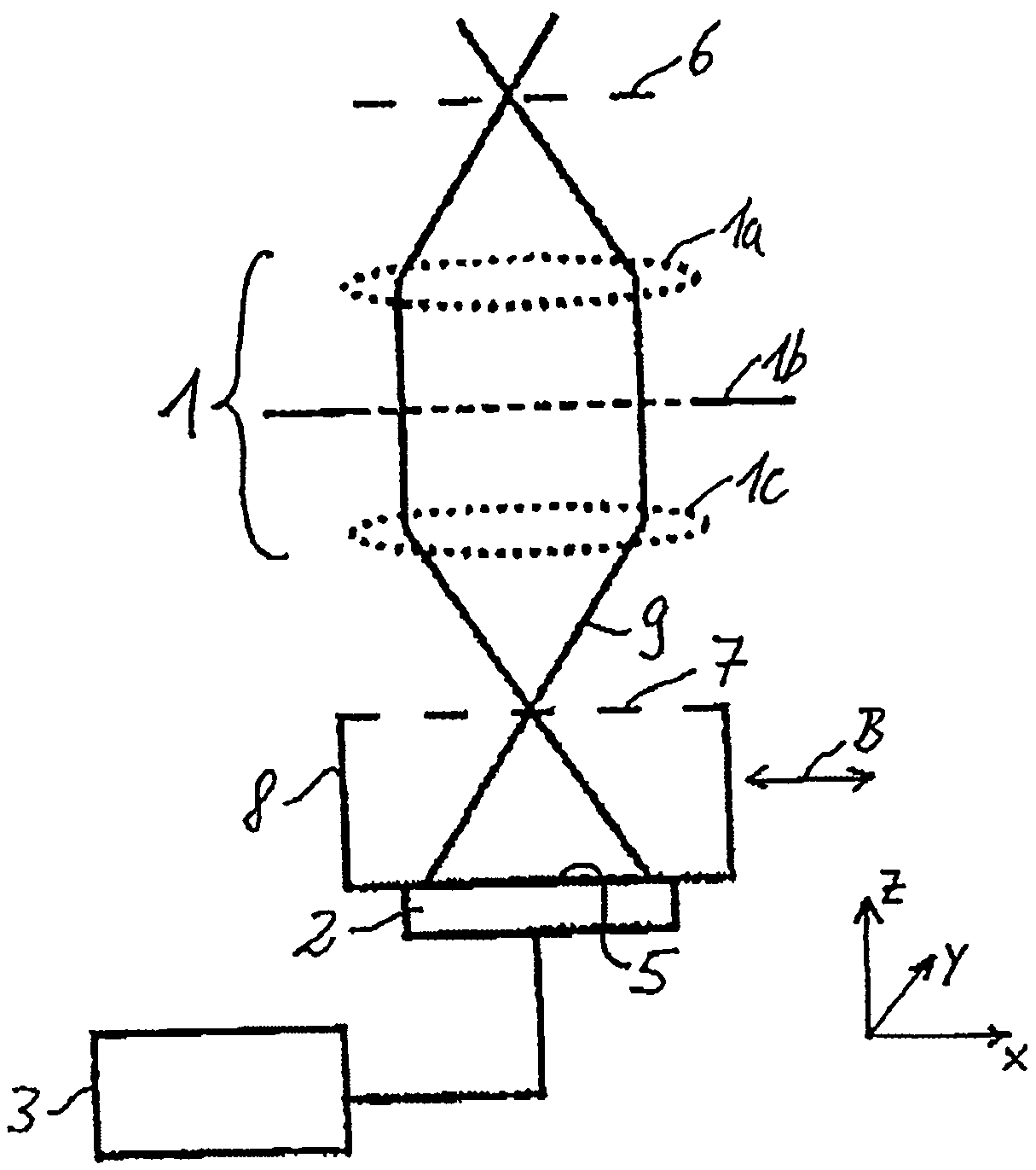
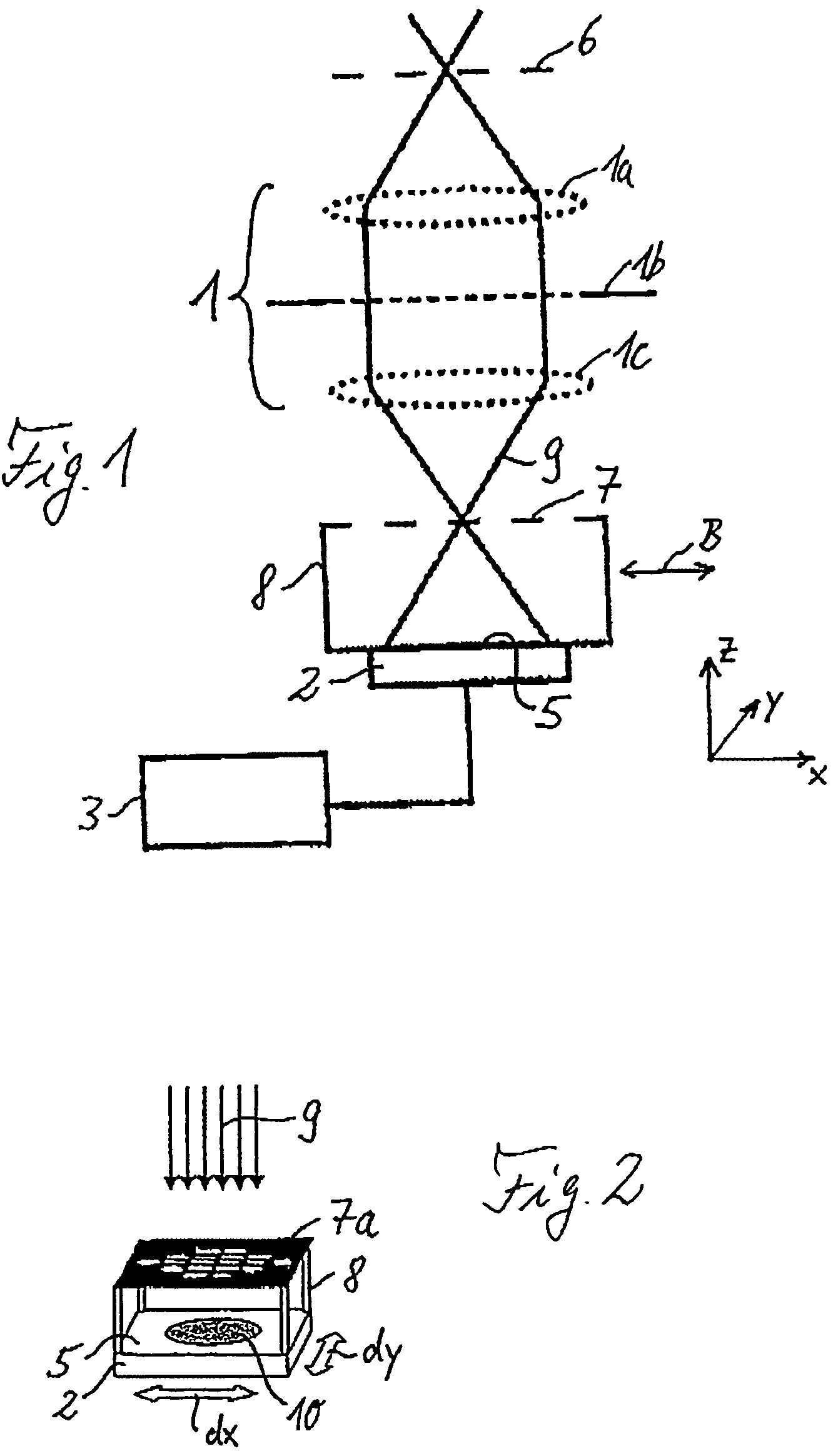
[0024]FIG. 1 illustrates a typical design of a device for wavefront measurement by means of shearing interferometry for the purpose of determining image errors and, in particular aberrations, using the example of a projection objective 1 of a microlithography projection exposure machine as optical imaging system to be measured. The objective 1 is represented in a simplified fashion by an object-side lens 1a, an objective pupil 1b and an image-side lens 1c. A coherence mask 6 is arranged on object side, preferably in the object plane of the objective 1. In a fashion corresponding thereto, a phase-shifting diffraction grating 7 is arranged on the image side, preferably in the image plane of the objective 1, such that it can move laterally in the xy-plane orthogonal to the z-direction of the optical axis of the system. The distorted pupil of the objective 1 is imaged onto a detector element 2, more precisely onto a detection plane 5 of the same. Coupled to the detector element 2, which...


PUM


Abstract

Device and method for wavefront measurement of an optical imaging system by means of phase-shifting interferometry, having a mask structure (6a) to be arranged on the object side, and / or a grating structure (7a) to be arranged on the image side. The object-side mask structure includes one or more one-dimensional mask structure patterns, and the image-side grating structure includes one or more two-dimensional grating structure patterns. Alternatively, conversely, the mask structure includes one or more two-dimensional patterns, and the grating structure includes one or more one-dimensional patterns. Additionally or alternatively, a pupil position offset caused by a lateral relative movement of the mask structure and detector element can be taken into account by back calculating the interferogram, respectively recorded by the detector element, using an associated phase-shift characteristic, or by a computational correction of wavefront derivatives, obtained from the recorded interferograms, in the direction of lateral movement. The method and / or the device can by used, for example, for determining aberration in the case of high-resolution projection objectives of microlithography exposure machines using shearing or point interferometry.

Description

[0001]The following disclosure is based on German Patent Application No. 103 16 123.6 filed on Apr. 4, 2003, which is incorporated into this application by reference.FIELD OF THE INVENTION[0002]The invention relates to a device for wavefront measurement of an optical imaging system by means of a phase-shifting interferometry technique, having a mask structure to be arranged on the object side, and a grating structure to be arranged on the image side, and to a method for wavefront measurement of an optical imaging system by means of a phase-shifting interferometry technique, wherein a phase-shifting structure and a detector element are moved laterally relative to the optical imaging system to be measured.BACKGROUND AND OBJECTS OF THE INVENTION[0003]Devices and methods of this type serve the purpose, for example, of determining the imaging quality and / or image errors of high-resolution optical imaging systems interferometrically with high precision. An important field of application i...

Claims


Application Information

Patent Timeline
Patent Type & Authority Patents(United States)
IPC IPC(8): G01B9/02G01J9/04
CPCG01J9/04G03F7/706G01M11/0271G01M11/0264
Inventor HAIDNER, HELMUTEMER, WOLFGANGHOCH, RAINERWEGMANN, ULRICHSCHRIEVER, MARTINGOEPPERT, MARKUS
Owner CARL ZEISS SMT GMBH
Why Eureka
Try Eureka