Hair removing device

a hair removal and device technology, applied in the field of hair removal devices, can solve the problems of detracting vibrations, and achieve the effects of avoiding vibrations that detract, allowing design flexibility to connect, and ensuring sufficient toleran

Inactive Publication Date: 2008-09-02
MATSUSHITA ELECTRIC WORKS LTD
View PDF16 Cites 15 Cited by
  • Summary
  • Abstract
  • Description
  • Claims
  • Application Information

AI Technical Summary

Benefits of technology

[0003]The above problem has been reduced in the present invention which provides an improved hair removing device which is capable of giving design flexibility to the connection between a housing and a detachable epilator head, without requiring a strict driving connection between a motor in the housing and a drive mechanism in the head. The hair removing device in accordance with the present invention includes the housing incorporating the rotary motor, and the epilator head detachable to the housing. The epilator head carries epilation members for epilation of a user's hairs and includes a drive mechanism powered by the motor to actuate the epilation members. The motor has an output rotor fixedly carrying a noncircular joint. The drive mechanism includes a coupler which is detachably connected to the joint to receive the rotary motion of the motor. The coupler is arranged coaxially with the joint and is movable along the axis of the joint together with the epilator head into and out of engagement with and from the joint, and the coupler is slidable along the axis of the joint while keeping the driving connection therebetween. Thus, the driving connection between the head and the motor can be established or disconnected simply by moving the coupler towards and away from the joint, while giving sufficient tolerance in the axial direction of the joint for keeping the driving connection. With this result, the driving connection can be easily established for successfully driving the epilation members even if there should be some gap in a mounting structure between the housing and the epilator head. Further, this simple slidable driving connection can be free from a harsh meshing engagement as seen in the gear connection, thereby avoiding the transmission of harsh vibrations from the epilator head to the housing for assuring a comfortable operation, in addition to reducing a noise.
[0005]The epilator head is preferred to carry a cylinder having a center axis along which a plurality of the epilation members are arranged. The drive mechanism includes a first linkage leading from the coupler for shifting the epilation members along the center axis towards and away from one another in order to pinch the hairs between the adjacent epilation members and at the same time for rotating the cylinder about the center axis to pluck the hairs pinched between the members. The drive mechanism also includes a second linkage leading from the coupler for oscillating the cylinder along the center axis to give optimum hair epilation efficiency. The cylinder is arranged to have its center axis lying substantially in a coplanar relation with the axis of the joint such that the cylinder can be assembled together with the coupler and the driving linkages into the epilator head of reduced thickness.
[0007]Further, the epilator head includes a base detachable to the housing and a frame mounting thereon a plurality of gears forming the first and second linkages in addition to the cylinder. The frame is supported to the base by way of spring means to be movable relative to the base against the bias of the spring means. Thus, vibrations occurring in the operation of the epilator head can be effectively absorbed by the spring means so as to make the housing relatively free from the vibrations, assuring a comfortable handling of the device.
[0008]The frame is movable in a direction along the axis of the joint together with the cylinder, i.e., floatingly supported to the base so that the cylinder can be depressed upon contact with the user's skin for easy and optimum epilation efficiency. The frame is movable also in a direction of the center axis for successfully absorbing the vibrations occurring in the axial direction of the cylinder due to the oscillating movement of the cylinder.

Problems solved by technology

With this gear connection, however, the device suffers from a strict dimensional tolerance between the gears, i.e., a distance between the axes of the gears for successfully transmitting the driving force from the motor to movable members in the head, which in turn requires a correspondingly strict detachable connection between the housing and the detachable head.
Further, when the head is operating under a heavy load, the gear connection is likely to transmit vibrations occurring in the heavy load operation of the head directly to the housing, thereby generating harsh vibrations which detract from a comfortable operation by the user grasping the housing.

Method used


Image

  • Hair removing device
  • Hair removing device
  • Hair removing device

Examples


Embodiment Construction

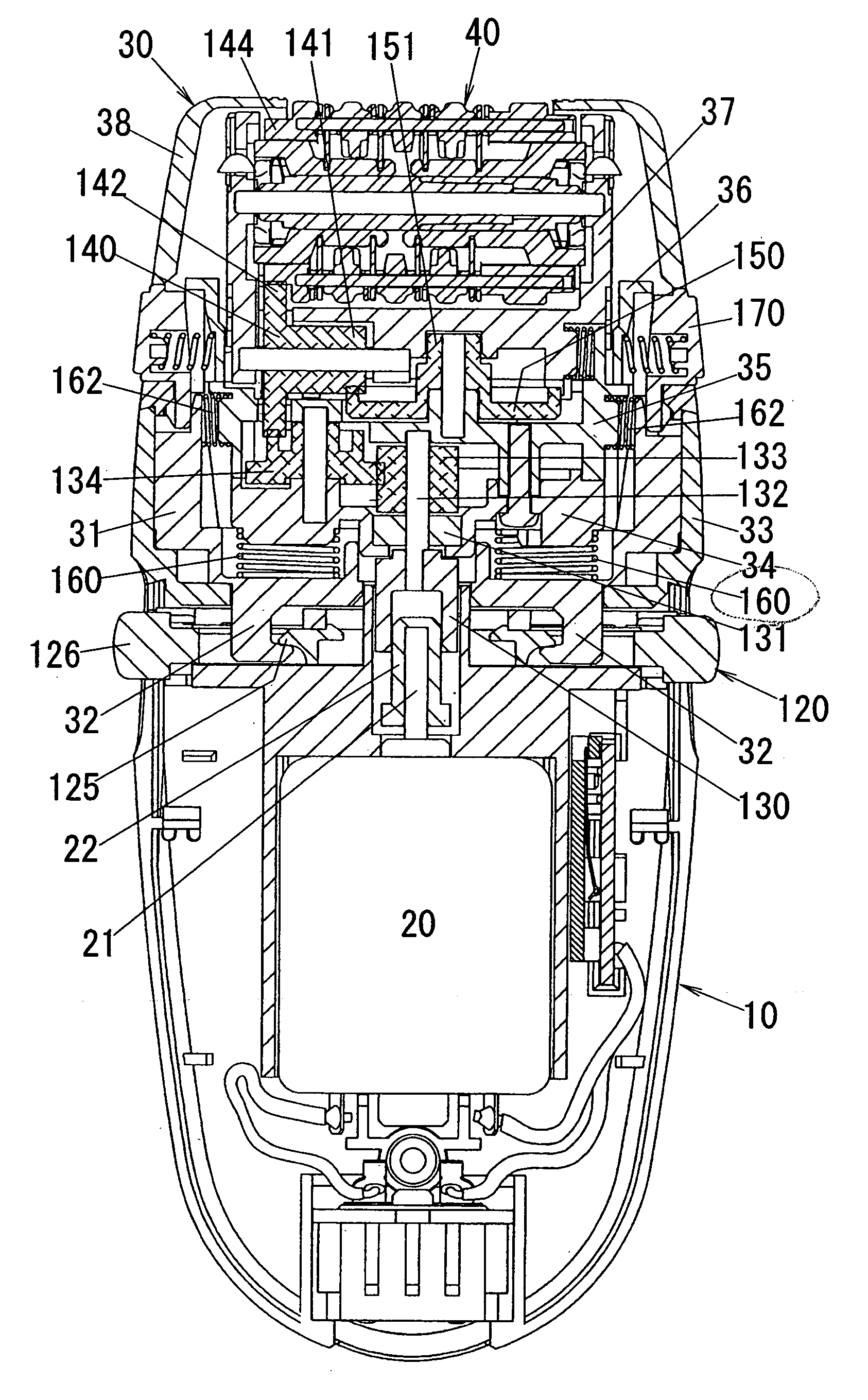
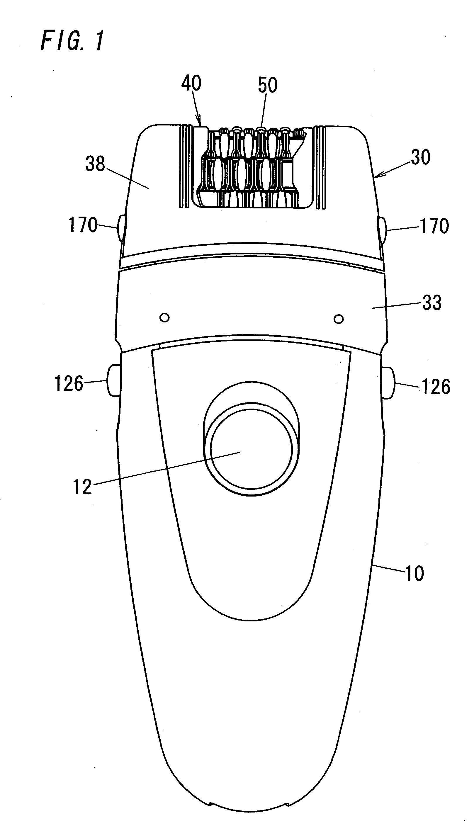
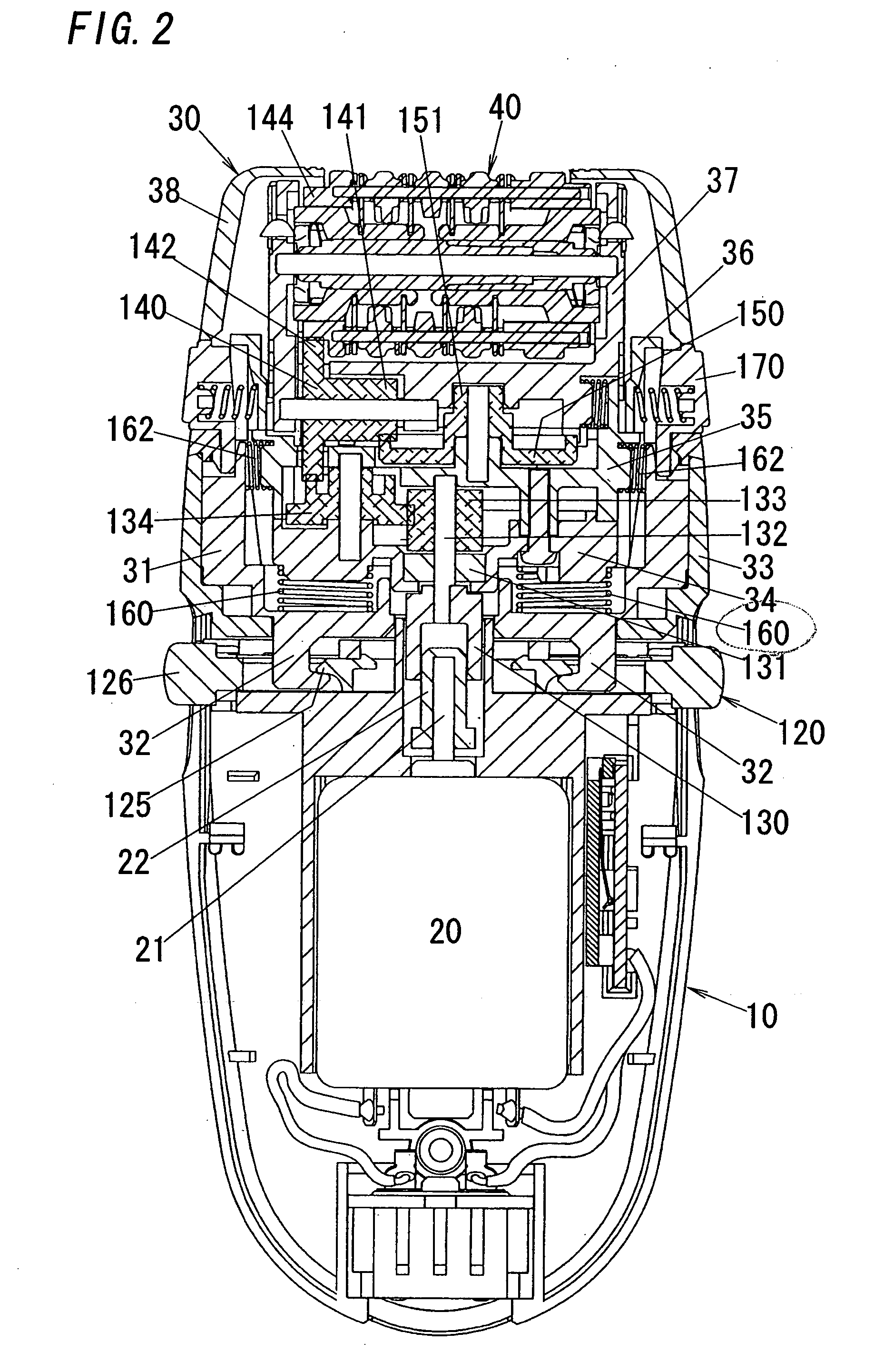
[0026]Referring now to FIGS. 1 and 10, there is shown a hand-held hair removing device in accordance with a preferred embodiment of the present invention. The device has a housing 10 which is designed to be grasped by a user's hand and to detachably mount thereon an epilator head 30 and a shaving head 300 selectively for epilating or plucking the hairs from a user's skin and cutting the hairs prior to epilating the hairs. The housing 10 accommodates an electric rotary motor 20 having a output rotor shaft 21 extending vertically in alignment with a center vertical axis of the housing for detachable driving connection to the epilator head 30 and shaving head 300 selectively mounted on top of the housing 10. The epilator head 30 and the shaving head 300 are analogous in its shape having an elongated width extending in a perpendicular relation to the vertical axis of the housing 10. The epilator head 30 carries a rotary cylinder 40 which is driven to rotate about its center axis, i.e., ...


PUM


Abstract

A hair removing device capable of selectively attaching an epilator head for hair epilation and a shaving head for hair cutting. The device includes the housing incorporating the rotary motor, and the epilator or shaving head detachable to the housing. The head includes a drive mechanism powered by the motor for hair epilation or cutting. The motor has an output rotor fixedly carrying a noncircular joint. The drive mechanism includes a coupler which is detachably connected to the joint to receive the rotary motion of the motor. The coupler is arranged coaxially with the joint and is movable along the axis of the joint together with the head into and out of engagement with and from the joint, and the coupler is slidable along the axis of the joint while keeping the driving connection therebetween.

Description

TECHNICAL FIELD[0001]The present invention is directed to a hair removing device for epilating hairs from a user's skin, and more particularly to a hair removing device with a detachable epilator head.BACKGROUND ART[0002]U.S. Pat. No. 4,960,422 discloses a hair removing device having a detachable epilator head that can be separated from a grip housing for cleaning the head, or for replacement with an analogous shaving head. A rotary motor is incorporated in the housing to provide a driving force of epilating or shaving the hairs. Due to the detachable nature of the device, the housing also includes a gear which is driven by the motor and is responsible for detachable meshing engagement with an associated gear provided in the epilator head or the shaving head. That is, the epilator head is drivingly connected to the motor by meshing engagement of the gears when the epilator head is attached to the housing. With this gear connection, however, the device suffers from a strict dimension...

Claims


Application Information

Patent Timeline
Patent Type & Authority Patents(United States)
IPC IPC(8): A61B17/50A45D26/00B26B19/02B26B19/16B26B19/26B26B19/38B26B19/48
CPCA45D26/0028B26B19/48B26B19/02A45D2026/0095A45D26/00
Inventor HASHIGUCHI, TETSUROUSUEYOSHI, HIDEKAZU
Owner MATSUSHITA ELECTRIC WORKS LTD
Why Eureka
Try Eureka