Multi-antenna system and antenna unit

a multi-antenna system and antenna unit technology, applied in diversity/multi-antenna systems, individual energised antenna arrays, wireless communication, etc., can solve the problems of large system size, large power loss, and extremely short electromagnetic wave reaching distance, so as to reduce the cost of dead zones and small power loss , the effect of miniaturizing the system

Inactive Publication Date: 2008-09-02
FUJITSU LTD
View PDF5 Cites 21 Cited by
  • Summary
  • Abstract
  • Description
  • Claims
  • Application Information

AI Technical Summary

Benefits of technology

[0014]The present invention has been developed in view of the aforementioned conventional technical problems. That is, an object of the present invention is to provide a technology capable of inexpensively reducing dead zones by branching radio signals input to / output from one base station to a plurality of antennas with small power losses or collecting radio signals from the plurality of antennas, and capable of miniaturizing a system.

Problems solved by technology

In a building or an underground shopping center, however, an electromagnetic wave reaching distance becomes extremely short because of a structure of a building.
Thus, large transmission power supplied from the base station device 301 has directly caused a large power loss.
Thus, with this configuration, the system has become extremely large as compared with the configuration of FIG. 1.

Method used


Image

  • Multi-antenna system and antenna unit
  • Multi-antenna system and antenna unit
  • Multi-antenna system and antenna unit

Examples


first embodiment

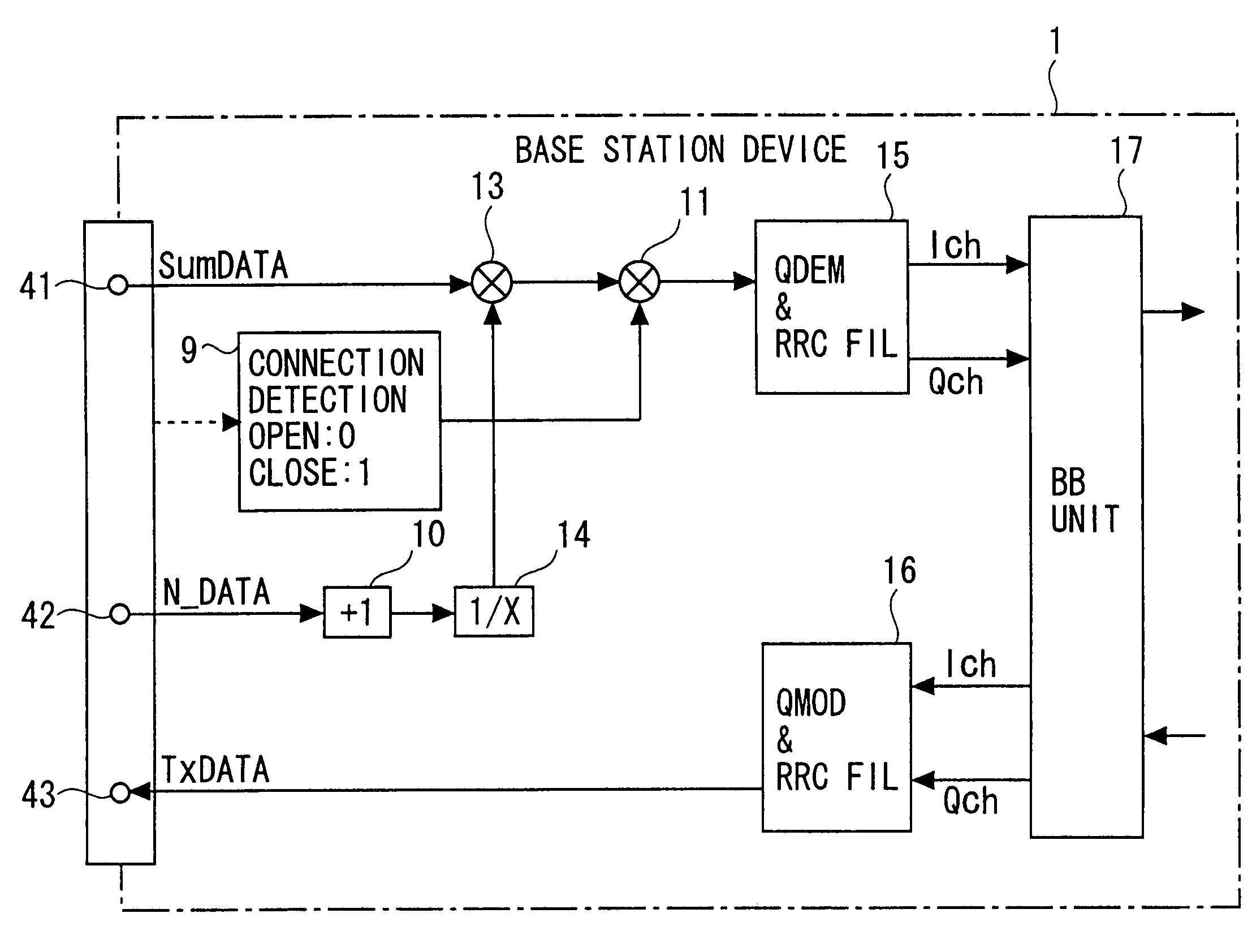
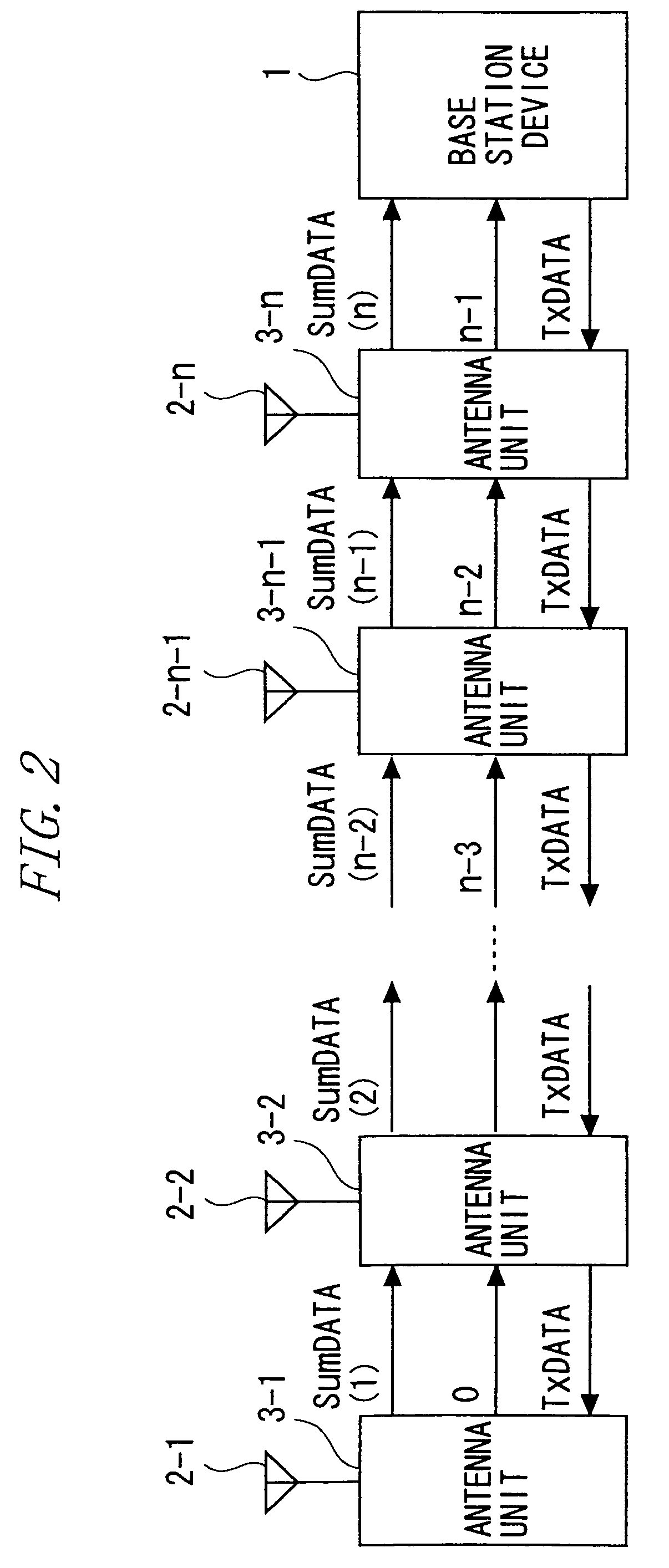
[0080]Hereinafter, a radio communication base station system (simply referred to as a base station system, hereinafter) according to a first embodiment of the present invention will be described with reference to FIGS. 2 to 4. According to this embodiment, the base station system is realized by combining a plurality of signal processing units called antenna units.

CONNECTION EXAMPLE

[0081]FIG. 2 shows a connection example of the antenna units of this base station system. As shown in FIG. 2, according to this embodiment, this base station system includes a base station device 1, antenna units 3-1, 3-2, . . . , 3-n (antenna units 3-1 and the like, hereinafter) linearly connected from the base station device 1, and antennas 2-1, 2-2, . . . , 2-n connected to the antenna units 3-1 and the like to transmit / receive radio signals.

[0082]In FIG. 2, a direction toward the base station device 1 is called an uplink direction (equivalent to a second direction). Additionally, in FIG. 2, a direction...

second embodiment

[0121]Hereinafter, a second embodiment of the present invention will be described with reference to FIGS. 5 to 8. The first embodiment has shown the configuration of the base station system where the plurality of antenna units 3-1 to 3-n are linearly connected. This embodiment will be described by way of a base station system where a plurality of antenna units are connected by being branched in a tree form. Other components and operations are similar to those of the base station system of the first embodiment. Thus, components similar to those of the first embodiment are denoted by similar reference symbols, and description thereof will be omitted. When necessary, reference will be made to FIGS. 2 to 4.

[0122]FIG. 5 shows a connection example of antenna units in the base station system. As shown in FIG. 5, according to this embodiment, the base station system includes a base station device 1, addition processing units 50 branched in a tree form from the base station device 1, and ant...

third embodiment

[0134]Hereinafter, a third embodiment of the present invention will be described with reference to FIGS. 9 and 10. The first embodiment has shown the configuration of the base station system where the plurality of antenna units 3-1 to 3-n are linearly connected. The digital added value (added digital data SumDATA) of the reception signals from the antenna units 3-1 to 3-n and the total number of connected antennas (number of connected antennas N_DATA) are transmitted to the base station device 1. Further, the base station device 1 calculates the average of the reception digital data based on the added digital data SumDATA and the number of connected antennas N_DATA, and performs digital quadrature demodulation.

[0135]This embodiment will be described by way of example of implementing average calculation of reception digital data in each antenna unit. Other components and operations are similar to those of the first embodiment. Thus, components similar to those of the first embodiment...


PUM


Abstract

A multi-antenna system comprising a plurality of linearly connected antenna units, and a base station device connected to at least one of the antenna units. The antenna units connected in a first direction or a second direction are combined to constitute a multi antenna. The multi-antenna system comprises a unit addition unit that adds one unit to number-of-connected-antenna-units information which is input from the first direction; a number-of-connections sending unit that sends the number-of-connected-antenna-units information, to which one unit has been added as described above, as the number-of-connected-antenna-units information in the second direction; a received data addition unit that adds input digital data, which is input from the first direction, to received digital data; an added-digital-data sending unit that sends the digital data, to which input digital data has been added, as input digital data in the second direction; and a transmission data sending unit that copies the transmission digital data, which is input from the second direction, and sends the copied digital data in the first direction.

Description

CROSS-REFERENCE TO RELATED APPLICATION[0001]This is a continuation of International Application PCT / JP2003 / 005612, filed on May 2, 2003. The disclosures of International Application PCT / JP2003 / 005612 including the specification, drawings and abstract are incorporated herein by reference.BACKGROUND OF THE INVENTION[0002]1. Technical Field[0003]The present invention relates to a radio communication base station.[0004]2. Background Art[0005]A wide-ranging communication enable area is required in mobile communication services for cellular phones or the like. In a building or an underground shopping center, however, an electromagnetic wave reaching distance becomes extremely short because of a structure of a building. Thus, an electromagnetic wave dead zone is easily created.[0006]In such a place, to reduce the dead zone of mobile communication, generally, many base stations or antennas must be installed (e.g., refer to Patent Document 1).[0007]FIG. 1 is a diagram showing a conventional ...

Claims


Application Information

Patent Timeline
Patent Type & Authority Patents(United States)
IPC IPC(8): H04M1/00H01Q21/08H04B1/3822H04B1/40H04B7/08H04W16/26H04W16/28H04W24/00
CPCH04B7/086H04B1/40H04B7/08
Inventor FUNAKUBO, TOSHIAKI
Owner FUJITSU LTD
Why Eureka
Try Eureka