Predictive emissions monitoring method

a technology of emissions monitoring and prediction method, applied in the direction of adaptive control, process and machine control, instruments, etc., can solve the problems of inconvenient operation, difficult maintenance, and difficult maintenance of continuous emissions monitoring system components such as gas analyzers, and achieve the effect of avoiding out-of-compliance operation, reducing the number of errors, and improving the accuracy of monitoring results

Active Publication Date: 2008-09-02
CMC SOLUTIONS
View PDF98 Cites 18 Cited by
  • Summary
  • Abstract
  • Description
  • Claims
  • Application Information

AI Technical Summary

Problems solved by technology

Continuous emissions monitoring system components such as gas analyzers are quite expensive, difficult to maintain, and difficult to keep properly calibrated.
This results in out-of-compliance operation and over-reporting of emissions.
For the most part, these PEM systems are complicated, relatively costly, and difficult to implement.

Method used


Image

  • Predictive emissions monitoring method
  • Predictive emissions monitoring method
  • Predictive emissions monitoring method

Examples


Embodiment Construction

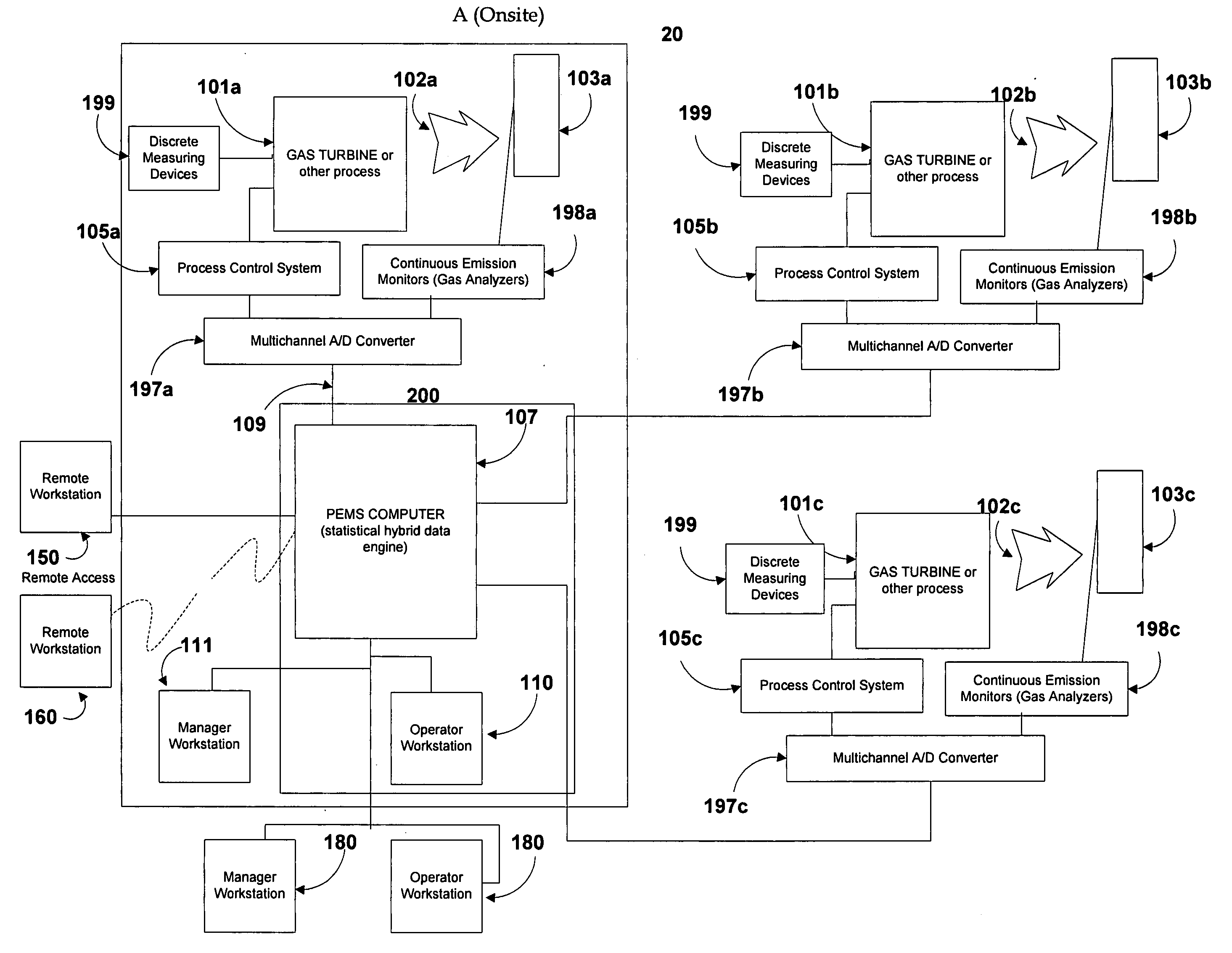
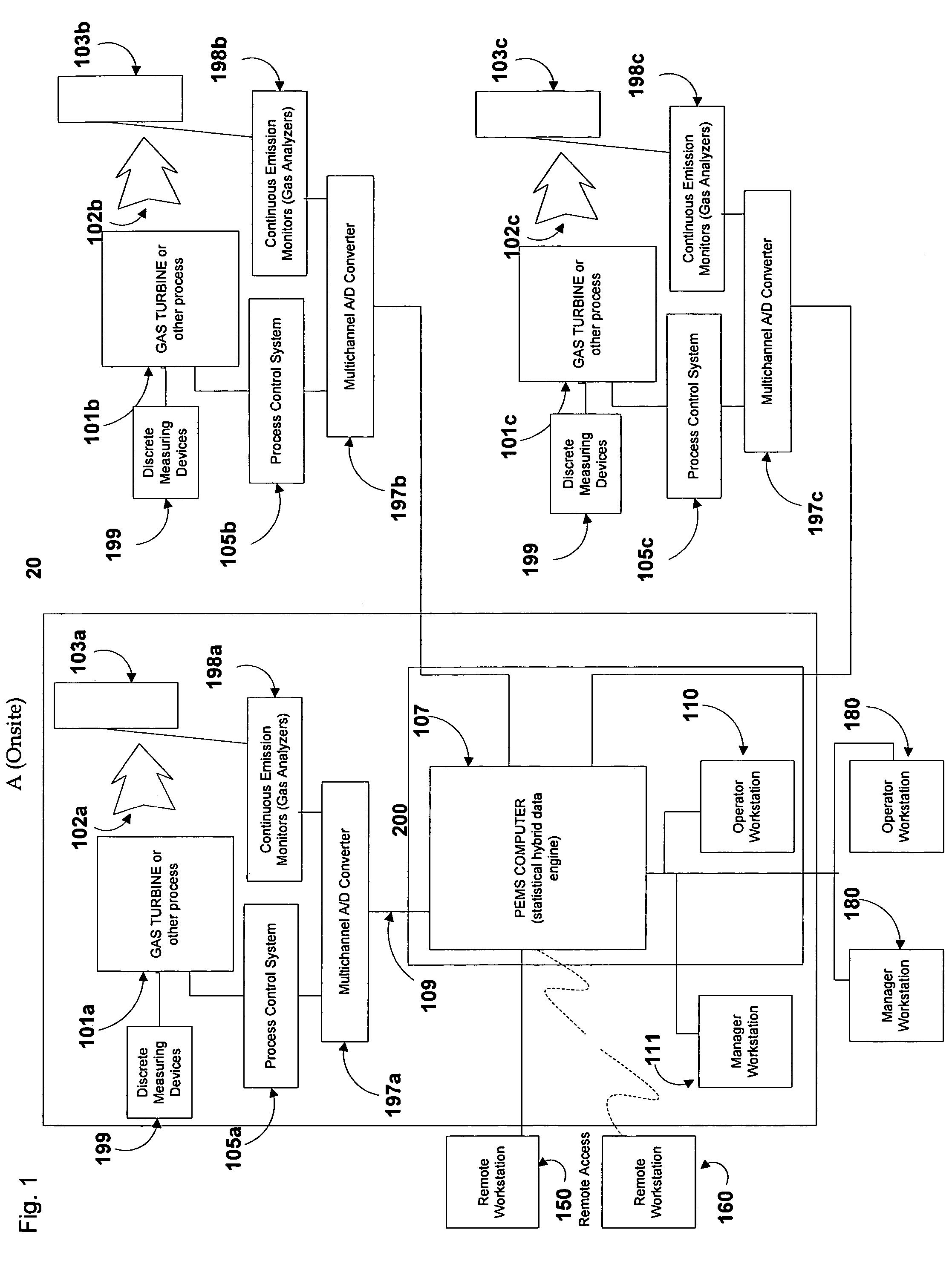
[0024]FIG. 1 is a schematic diagram of a system 20 in accordance with the present invention for monitoring, predicting, and controlling system process variables and emissions in one or more continuous or batch processes and / or emissions sources. The system shown in FIG. 1 is configured for centralized monitoring and management of multiple processes or emissions sources. Referring to FIG. 1, emissions source(s) 101(a)-(c) each run in a continuous or batch process which utilizes raw materials (for example, coal or fuel oil) to produce a measurable output (energy or other products). Emission sources 101(a)-(c) can take any form including reciprocating diesel engines, reciprocating gas engines, gas turbines, steam turbines, package boilers, waste heat boilers, solar-based generators, wind-based generators, fuel-cell based generators, or any other devices that are capable of transforming any form of potential energy into electricity while exhausting pollutant emissions 102 to the atmosph...


PUM


Abstract

A method for predicting emissions from an emissions source. Test values of process variables relating to operation of the emissions source are gathered, along with corresponding time-correlated test values of the emissions variable to be predicted. Using the test values of the process variables, test values of a plurality of first coefficients are calculated for each process variable and associated with the process variable, and test values of a plurality of second coefficients are calculated for each value of each process variable and associated with the value of the process variable. Comparison values of the process variables relating to operation of the emissions source are gathered, along with corresponding time-correlated comparison values of the emissions variable to be predicted. Using the comparison values of the process variables, comparison values of a plurality of first coefficients are calculated for each process variable and associated with the process variable, and comparison values of a plurality of second coefficients are calculated for each value of each process variable and associated with the value of the process variable. Predetermined combinations of the comparison values of the variables and their associated coefficients are then iteratively compared with the test values of the respective variables and associated coefficients. Where the comparison yields matches between the comparison values and test values of the variables and their associated coefficients, the test values of the emissions variable associated with the matched test values of the variables are averaged and assigned as a predicted value of the emissions variable.

Description

CROSS REFERENCE TO RELATED APPLICATIONS[0001]This application claims the benefit of provisional application Ser. No. 60 / 663,461, filed on Mar. 18, 2005.REFERENCE TO A COMPUTER PROGRAM LISTING APPENDIX[0002]An original compact disc and a duplicate compact disc, each disc containing a computer program listing appendix and an incorporation-by-reference statement linking the compact disc with the present application, are being filed with this application. The contents of the compact discs are incorporated into this application by reference. The contents of the compact discs are identical. Per 37 CFR §1.52(e)(5), the files contained on each compact disk, along with the dates of creation and file sizes (in bytes), is listed as follows:[0003]CMCpatent.PEMSsq12.txt 17 kb Sep. 8, 2006[0004]11 384077.txt1 kb Sep. 8, 2006FIELD OF THE INVENTION[0005]The present invention relates to the monitoring and control of processes and to predictive models for their behavior, and more particularly, to a p...

Claims


Application Information

Patent Timeline
Patent Type & Authority Patents(United States)
IPC IPC(8): G05B21/00G01R21/00
CPCG05B17/02
Inventor SWANSON, BRIAN G.
Owner CMC SOLUTIONS
Why Eureka
Try Eureka