Autonomous matching test system for integral time of space camera in super-agility dynamic imaging

A technology of integration time and imaging space, which is applied in the field of self-matching test system of camera integration time in ultra-agile dynamic imaging space, which can solve the problems of poor control accuracy and rotation stability, difficulty in simulating dynamic imaging mode, limited rotational speed of mechanical rotating shaft targets, etc. problem, to achieve the effect of ensuring sufficiency, eliminating delay, and realizing synchronization

Active Publication Date: 2018-11-27
BEIJING RES INST OF SPATIAL MECHANICAL & ELECTRICAL TECH
View PDF8 Cites 9 Cited by
  • Summary
  • Abstract
  • Description
  • Claims
  • Application Information

AI Technical Summary

Problems solved by technology

[0004] The technical problem solved by the present invention is: to overcome the deficiencies of the prior art, to provide an ultra-agile imaging space camera integration time autonomous matching test system, which overcomes the limited rotational speed of the mechanical shaft target in the existing test system, the control accuracy and the Rotational stability is poor, it is difficult to simulate various complex imaging modes in motion, and bottlenecks such as poor synchronization between simulated scene motion and camera integration time enable various complex imaging modes, especially ultra-agile imaging modes in motion The on-orbit dynamic imaging performance evaluation and verification of the camera improves the accuracy and reliability of the on-orbit performance estimation of remote sensing satellites and camera subsystems

Method used


Image

  • Autonomous matching test system for integral time of space camera in super-agility dynamic imaging
  • Autonomous matching test system for integral time of space camera in super-agility dynamic imaging
  • Autonomous matching test system for integral time of space camera in super-agility dynamic imaging

Examples


Embodiment Construction

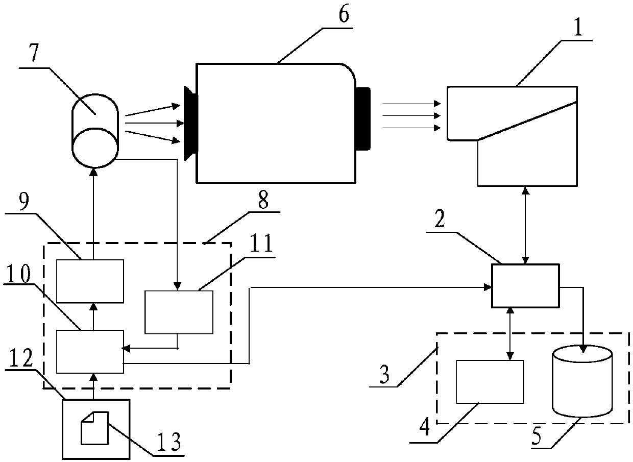
[0040] Aiming at the deficiencies of the prior art, the present invention proposes a super-agile imaging space camera integration time autonomous matching test system, including four parts: the space camera subsystem, the camera ground detection subsystem, the collimator and the dynamic scene simulation subsystem. .

[0041] The space camera subsystem includes the camera body and camera electronics. The camera body includes a camera lens, a camera focal plane and a supporting frame. The camera lens gathers the parallel light from the collimator on the focal plane of the camera, and the focal plane of the camera converts the light signal into an electrical signal, and the supporting frame is used to connect the camera lens and the focal plane of the camera, and each part is composed of a complete structure; the camera Electronics include camera integrated electronics unit and image processing unit. The integrated electronic unit receives instructions from the control and dete...


PUM


Abstract

The invention relates to an autonomous matching test system for the integral time of a space camera in super-agility dynamic imaging, which comprises a space camera subsystem, a camera ground detection subsystem, a collimator and a dynamic scene simulation subsystem, wherein the space camera subsystem comprises a camera main body and camera electronics, the camera main body comprises a camera lens, a camera focal plane and a support frame, the camera electronics comprises a camera integrated electronic unit and an image processing unit, the ground detection subsystem comprises a control detection unit and an image acquisition unit, and the dynamic scene simulation subsystem comprises a high-precision low-disturbance rotating axis target, a target control system and an upper computer. The camera integral time adopts an external trigger mode, and the correlation between the camera integral time and the simulated scene movement is achieved; the time delay is eliminated by the combinationof software and hardware from the perspective of the test system, the synchronization of the simulated scene movement and the camera imaging is realized, and the adequacy of the ground test verification test is guaranteed.

Description

technical field [0001] The invention relates to the technical field of space optical imaging, in particular to an autonomous matching test system for integration time of an ultra-agile imaging space camera in motion. Background technique [0002] The traditional remote sensing satellite imaging mode is that the camera starts imaging after the platform attitude maneuver is in place. In recent years, with the development of attitude control technology, the mobility and stability of remote sensing satellites have been continuously improved, and an ultra-agile imaging mode in motion will be realized, which can greatly increase the effective information density acquired by satellites, and improve the flexibility and observation efficiency of satellites. , has important application prospects. [0003] However, the existing ground test environment and test methods are not enough to effectively test the autonomous matching performance of camera integration time in ultra-agile imagi...

Claims


Application Information

Patent Timeline
Patent Type & Authority Applications(China)
IPC IPC(8): G01M11/02
CPCG01M11/00
Inventor 杨沐程少园于飞高凌雁姜宏佳付强强吴俊孙世君
Owner BEIJING RES INST OF SPATIAL MECHANICAL & ELECTRICAL TECH
Why Eureka
Try Eureka