Bus power device and power-source control method

a power supply and power supply technology, applied in the direction of liquid/fluent solid measurement, instruments, transportation and packaging, etc., can solve the problems of inability to understand the accuracy of the battery remaining level, inability to avoid the inoperative state due to the voltage drop, and failure to opera

Inactive Publication Date: 2008-09-02
FUJITSU LTD
View PDF20 Cites 25 Cited by
  • Summary
  • Abstract
  • Description
  • Claims
  • Application Information

AI Technical Summary

Problems solved by technology

This has a problem in that the current supplied from the USB-corresponding device 10 to the bus power device 20 may exceed a predetermined value (500 mA), leading to a malfunction or an operation failure.
Therefore, the inoperative state due to the voltage drop cannot be avoided.
Therefore, an accurate battery remaining level cannot be understood.
Therefore, even when it is necessary to charge in a short time, a quick charging cannot be achieved.
Therefore, the bus power device 50 cannot be used without the separate power source.

Method used


Image

  • Bus power device and power-source control method
  • Bus power device and power-source control method
  • Bus power device and power-source control method

Examples


first embodiment

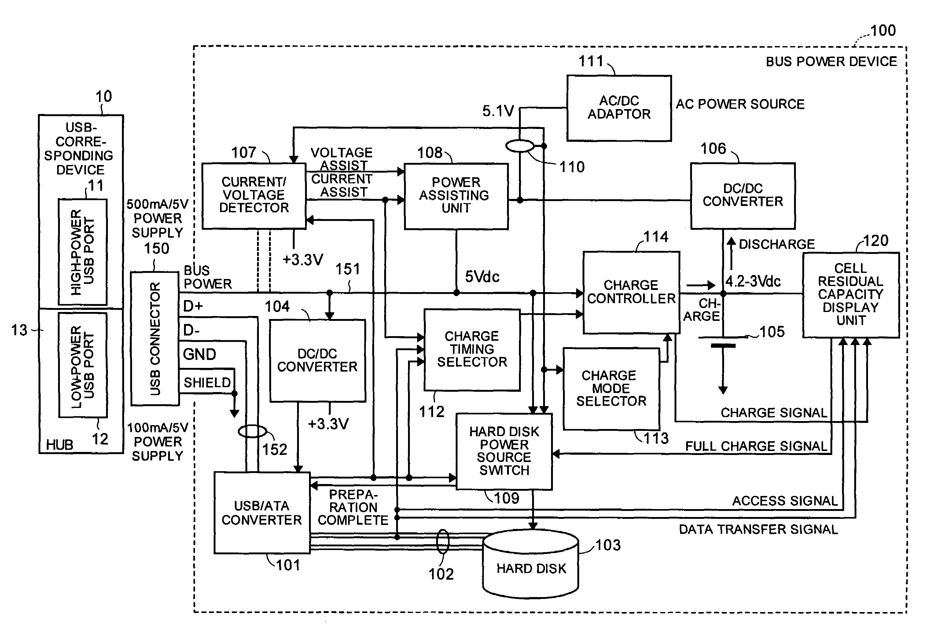
[0063]FIG. 1 is a block diagram of a configuration of a bus power device according to the present invention. In the drawing, like reference numerals as those in FIG. 9 designate like parts, and their explanation is omitted. In the drawing, a bus power device 100 is provided in place of the bus power device 40 shown in FIG. 9.

[0064]The bus power device 100 is a hard disk drive unit as one USB device, and is driven with high power (2.5 watts (500 mA / 5 V)) supplied from the USB-corresponding device 10 via a USB connector 150 connected to the high-power USB port 11 or supplied from an AC / DC adaptor 111 described later.

[0065]The USB connector 150 is based on the USB interface standard, and is connected to the high-power USB port 11 during a normal use of the bus power device 100. When the USB connector 150 is connected to the low-power USB port 12, and even when the AC / DC adaptor 111 is not present, the bus power device 100 can operate using a secondary battery 105.

[0066]The USB connecto...

second embodiment

[0135]FIG. 5 is a block diagram of a configuration of a bus power device according to the In the drawing, like reference numerals as those in FIG. 1 designate like parts, and their explanation is omitted. A bus power device 200 shown in the drawing has a compulsory charge switch 201 additionally, and a charge controller 202 instead of the charge controller 114 shown in FIG. 1.

[0136]The compulsory charge switch 201 is operated by a user to carry out the compulsory charge. The charge controller 202 has the function of carrying out the normal charge and the rapid charge that the charge controller 114 (see FIG. 1) has, and a function of carrying out the compulsory charge when the compulsory charge switch 201 is turned on.

[0137]The charge operation by the bus power device 200 shown in FIG. 5 is explained with reference to a flowchart shown in FIG. 6. At step SE1 shown in the drawing, the USB connector 150 is connected to the high-power USB port 11, and is plugged in.

[0138]At step SE2, t...


PUM


Abstract

A bus power device includes a connector that is connected to a port of a host apparatus compliant with a predetermined interface standard; a current / voltage detecting unit that detects a current / voltage supplied from the host apparatus to a bus power line via the port and the connector; and a power assisting unit that assists a current to the bus power line based on a result of comparison between the current detected by the current / voltage detecting unit and a threshold current, and assists a voltage to the bus power line by an amount of shortfalls in the voltage based on a result of comparison between the voltage detected by the current / voltage detecting unit and a threshold voltage.

Description

[0001]This is a continuation of International PCT Application No. PCT / JP03 / 03836 filed Mar. 27, 2003.BACKGROUND OF THE INVENTION[0002]1) Field of the Invention[0003]The present invention relates to a bus power device based on an interface standard of universal serial bus (USB), Institute of Electrical and Electronics Engineers (IEEE) 1394, and the like. More particularly, the present invention relates to a bus power device and a power-source control method that can avoid an inoperative state due to a voltage drop or the like, figure out a battery remaining level according to an operation status, and charge the battery quickly.[0004]2) Description of the Related Art[0005]Recently, as an interface to connect a peripheral device to a personal computer, the USB interface standard attracts attention. The USB interface standard has a characteristic that the interface can connect maximum of 127 USB devices in a tree structure.[0006]FIG. 7 is a block diagram of a configuration of a conventi...

Claims


Application Information

Patent Timeline
Patent Type & Authority Patents(United States)
IPC IPC(8): G06F1/00G06F1/26
CPCG06F1/266
Inventor NAKAJIMA, KENJIOOBA, KAZUHIDESUZUKI, MASAMICHI
Owner FUJITSU LTD
Why Eureka
Try Eureka