Firearm mount with embedded laser sight

a laser sight and mount technology, applied in the field of laser sights, can solve the problems of displace laser sights farther from firearm barrels, laser sights that are not available in all handguns, and significant targeting errors approximating initial offset, so as to reduce the size of accessory mounts, minimize the offset of laser sights, and reduce the effect of encumbrances

Active Publication Date: 2008-09-09
CROSMAN CORP
View PDF23 Cites 66 Cited by
  • Summary
  • Abstract
  • Description
  • Claims
  • Application Information

AI Technical Summary

Benefits of technology

[0007]The invention exploits space occupied by accessory mounts to construct sub-mountings for laser sights for such purposes as minimizing the offset of the laser sights from barrels, protecting the laser sights from exposure to jarring, and reducing encumbrances presented by the laser sights to the safe handling and operation of firearms. The accessory mounts, which present rails or other features for mounting accessories, can be integral parts of the firearms or can be attached as appendages to the firearms. The laser sights are preferably embedded within the accessory mounts without interfering with their function as primary or secondary mounts for attaching accessories to the firearms and also preferably without increasing the size of the accessory mounts.

Problems solved by technology

At close distances, the offset can result in a significant targeting error approximating the initial offset.
However, such built-in mounting locations are not available in all handguns, so laser sights have also been externally mounted from both conventional rails and special adapters.
In addition, the receptors used for engaging the rails can take up more space and displace the laser sights farther from firearm barrels.
The known laser sight modules mounted in this way are also exposed to jarring and can encumber the handling or operation of firearms, particularly as the laser sights are mounted at increasing offset from firearm barrels.

Method used


Image

  • Firearm mount with embedded laser sight
  • Firearm mount with embedded laser sight
  • Firearm mount with embedded laser sight

Examples


Embodiment Construction

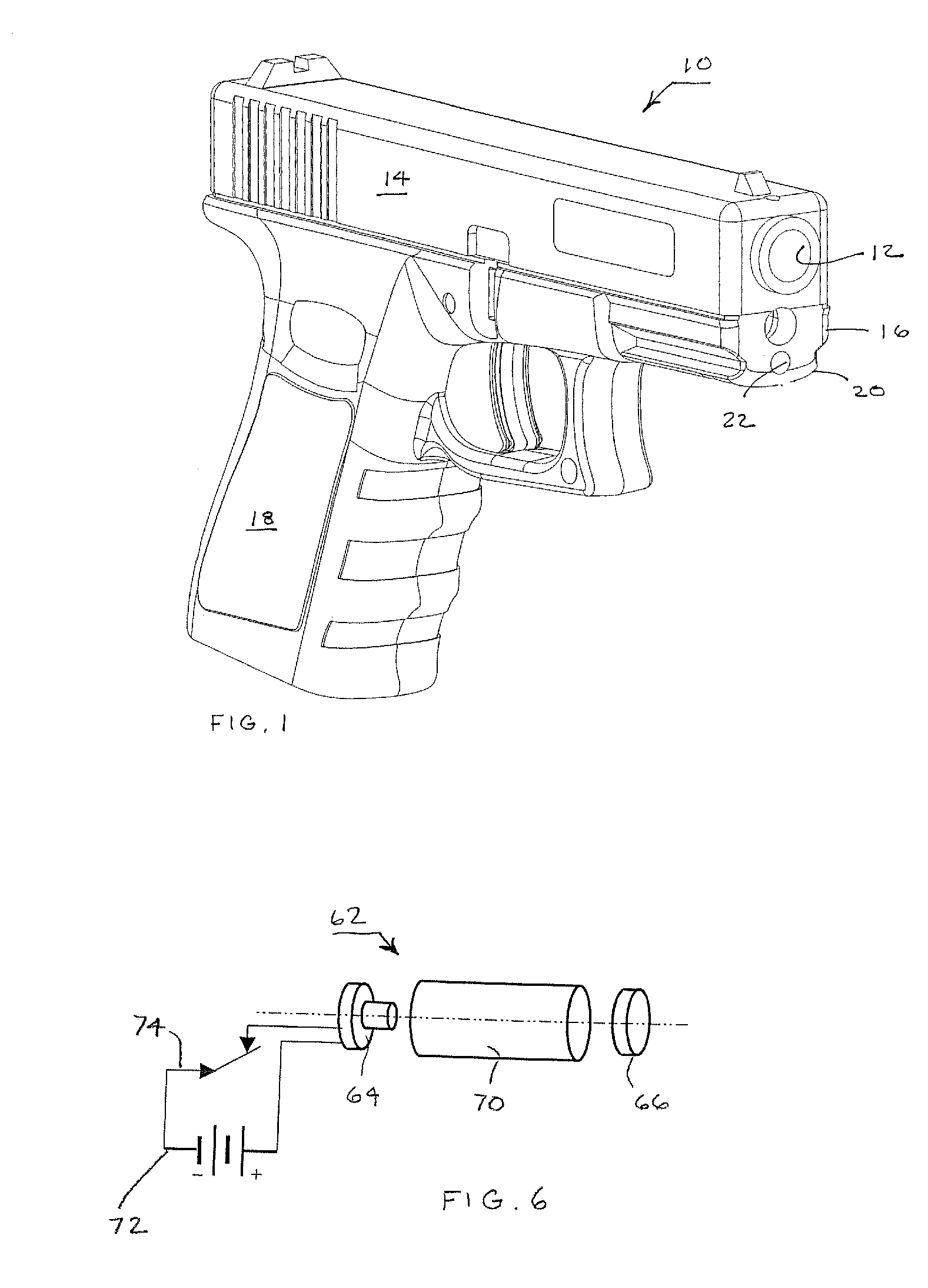
[0028]A conventional pistol 10 depicted in FIG. 1 includes the usual features of a barrel 12, a slide 14, and a receiver (or frame) 16 with an integral grip 18 as well as an accessory mount formed in the receiver 16 as a dovetail rail 20. Various accessories can be mounted from the dovetail rail 20 including tactical lights, laser sight modules, and supporting devices. However, the invention as shown in FIG. 1 modifies the dovetail rail 20 to house a laser sight 22.

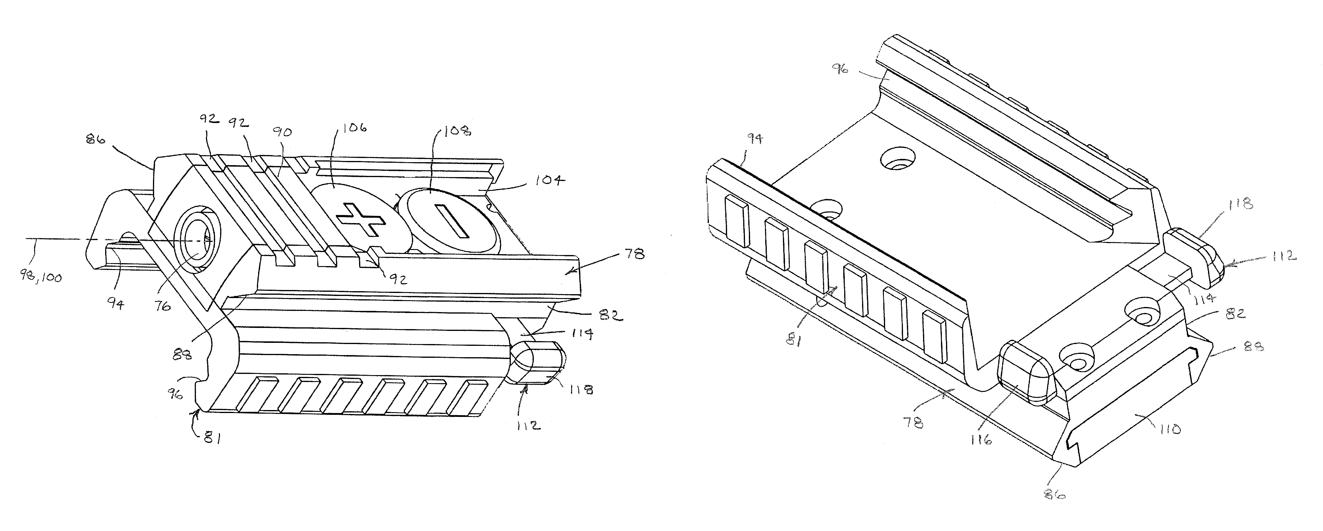
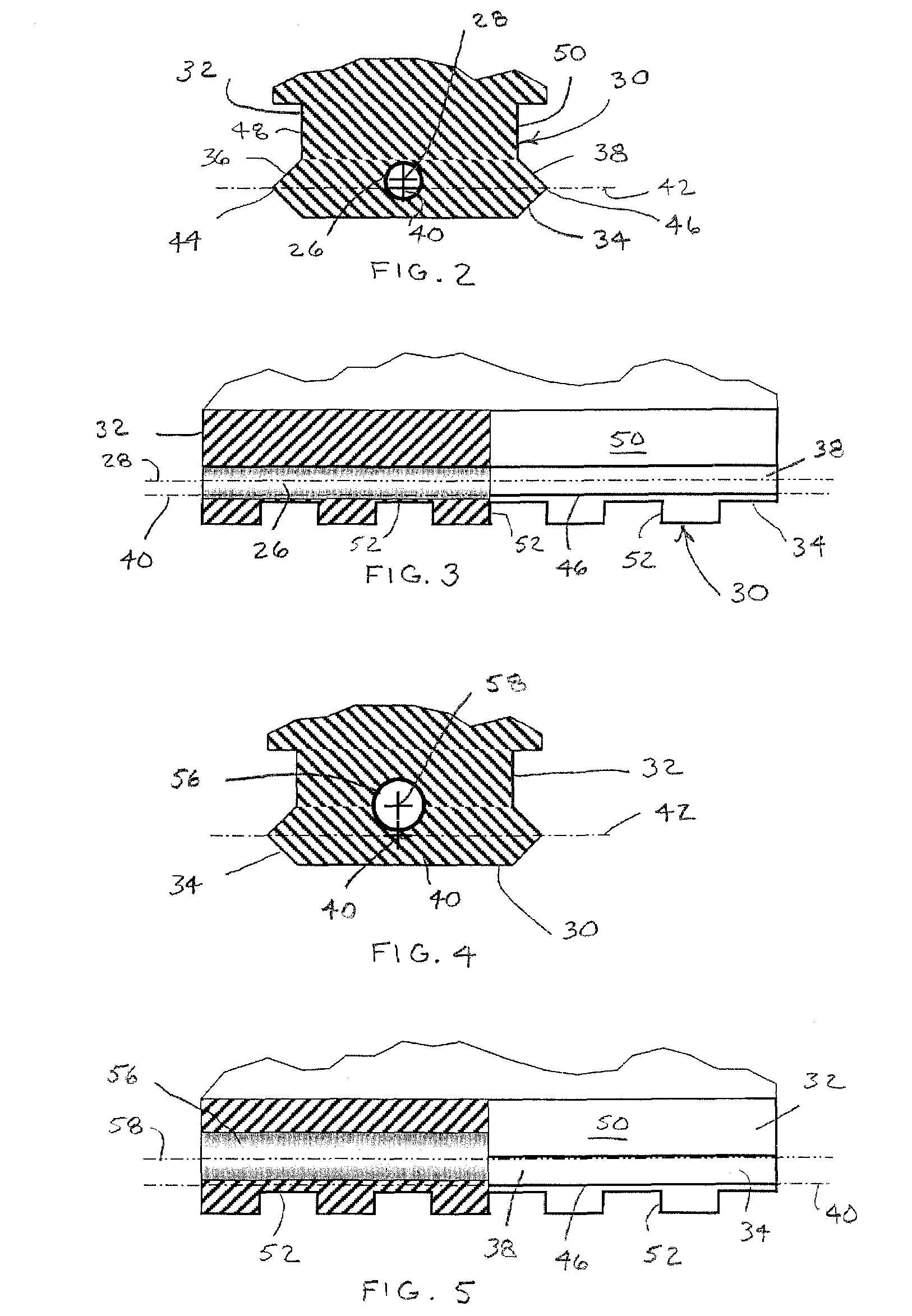
[0029]FIGS. 2 and 3 depict enlarged views of an alternative dovetail rail 30 within which a laser sight 26 is similarly housed. The dovetail rail 30 has the conventional configuration of a Picatinny rail having a T-shaped profile. A pedestal 32 (forming the base of the T) supports an overhanging platform 34 (forming the crossbar of the T) that has tapered sidewalls 36 and 38 extending without interruption along a longitudinal axis 40 of the dovetail rail 30. The longitudinal axis 40 is generally aligned with a barrel of a...


PUM


Abstract

A laser sight is embedded in a mounting rail otherwise used for attaching accessories to small arms discharge devices such as pistols or rifles. The mounting rail has a transverse profile that extends along an axis of the mounting rail for engaging mating features of the accessories. The laser sight is located at least partly within the transverse profile of the mounting rail and has a sighting axis that extends substantially parallel to the axis of the mounting rail.

Description

FIELD OF THE INVENTION [0001]The invention relates to laser sights and their mountings on firearms or other small-arm dischargeable devices.BACKGROUND OF THE INVENTION [0002]Laser sights are particularly effective as sighting devices because the lasers illuminate spots on their targets and do not require users to align an eye with a sighting device, which can limit or obscure the user's view of the targets or their surroundings. When mounted on firearms, the laser sights emit beams that are directed along the expected flight paths of projectiles discharged from the firearms. However, the laser sights are necessarily mounted offset from the firearm barrels, so the laser beams extend generally parallel but offset from the initial flight paths of the projectiles. At close distances, the offset can result in a significant targeting error approximating the initial offset. Small angular adjustments of the laser sights can compensate for the offset at longer distances.[0003]Particularly fo...

Claims


Application Information

Patent Timeline
Patent Type & Authority Patents(United States)
IPC IPC(8): F41G1/34F41G11/00
CPCF41G11/003F41G1/35
Inventor HOUDE-WALTER, WILLIAM R.
Owner CROSMAN CORP
Why Eureka
Try Eureka