Liquid ejection head, image forming apparatus and method of manufacturing liquid ejection head

a liquid ejection head and image forming technology, applied in the direction of printing, inking apparatus, etc., can solve the problems of difficult to ensure sufficient space for electrical wires, difficult to position wiring of this kind at high density, and difficult to eject electrical wires at the same surface. , to achieve the effect of reliable electrical connection and improved liquid ejection head production yield

Inactive Publication Date: 2008-09-09
FUJIFILM CORP
View PDF14 Cites 4 Cited by
  • Summary
  • Abstract
  • Description
  • Claims
  • Application Information

AI Technical Summary

Benefits of technology

[0017]The present invention was devised with the foregoing circumstances in view, an object thereof being to provide a liquid ejection head, an image forming apparatus, and a method of manufacturing a liquid ejection head that the bonding sections between piezoelectric elements and wiring members can have reliable electrical conductions and a reliable insulation against liquid, when wiring members are provided in such a manner that the wiring members pass through a common liquid chamber.

Problems solved by technology

However, if the density of the nozzles is increased in a conventional print head composition, there is a problem in that the electrical wires cannot be patterned onto the same surface as in the prior art, due to the increase in the number of electrical wires, such as the wires of the piezoelectric elements.
Thereby, when the nozzles are formed to high density, it is difficult to ensure sufficient space for the electrical wires.
However, the wiring does not envisage a matrix-type nozzle arrangement, and hence it is difficult to position wiring of this kind at high density.
Therefore, when the density of the nozzles is increased, it is necessary for reserving a larger space for the electrodes, and hence there are restrictions on the design of the common liquid chamber provided in the print head.
For example, in the case in which the common liquid chamber is reduced in size, when a large number of nozzles are driven at a high frequency, the ink supply from the common liquid chamber to the respective pressure chambers cannot keep up with the demand, and hence it becomes impossible to eject ink droplets from the nozzles.
Therefore, when the density of the nozzles is increased, there is a risk that the speed of ink supply will not be sufficient.
In particular, since the ink supply layer is constituted by a porous member, the print head is not suitable for ejection of high-viscosity ink.

Method used


Image

  • Liquid ejection head, image forming apparatus and method of manufacturing liquid ejection head
  • Liquid ejection head, image forming apparatus and method of manufacturing liquid ejection head
  • Liquid ejection head, image forming apparatus and method of manufacturing liquid ejection head

Examples


first embodiment

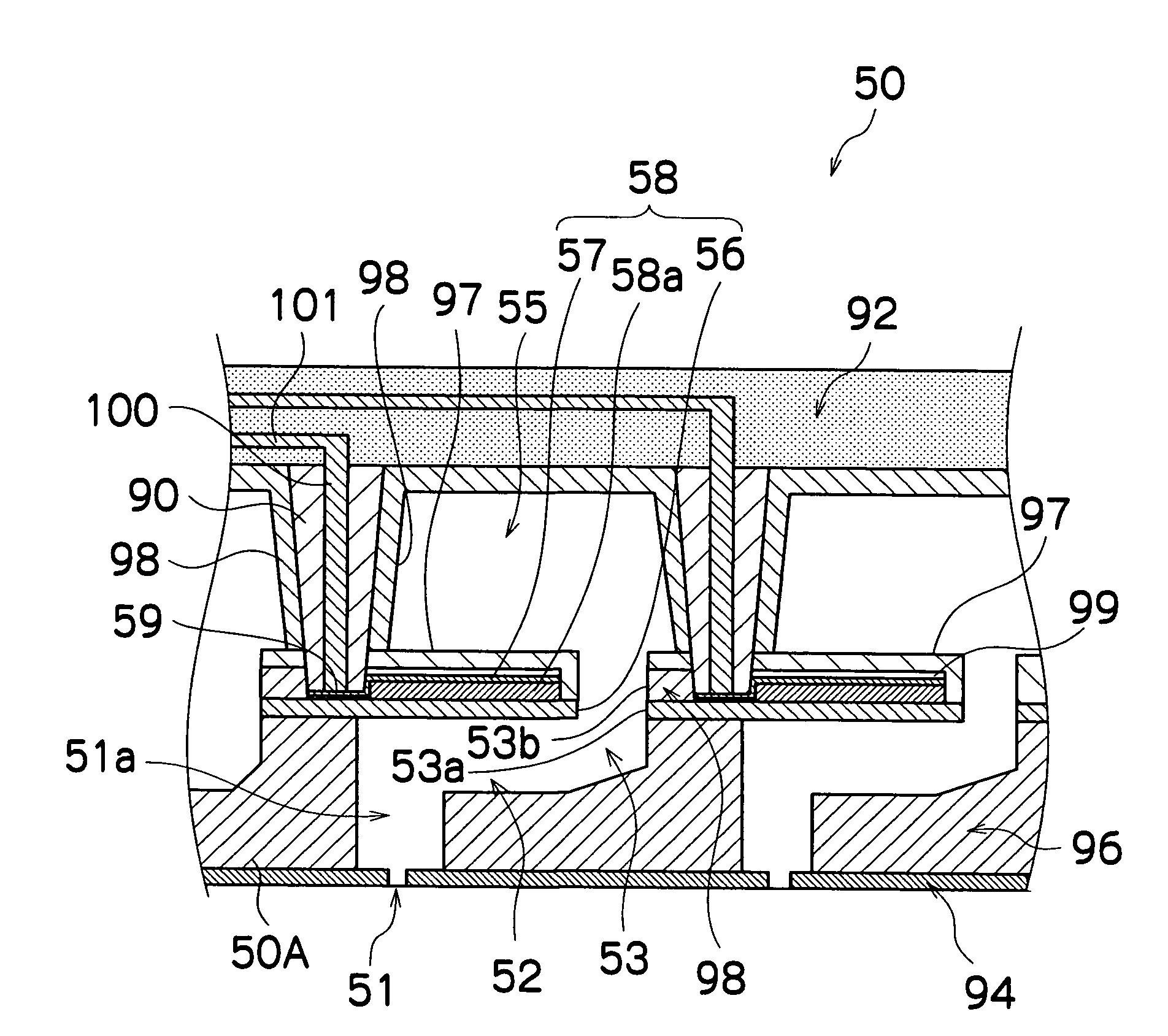
[0147]FIG. 9 is an enlarged diagram of a peripheral area of a bonding section between a piezoelectric element wire 90 and an electrode pad 59 in the present invention.

[0148]The adhesive 106 used for connecting the piezoelectric element wires 90 with the electrode pads 59 is made of a non-conductive resin 104 which contains conductive particles 102. For example, a commercially available epoxy resin, such as anisotropically conductive adhesive, may be used as the adhesive 106. Epoxy-based adhesives have high chemical resistance, and as in the present embodiment, they are suitable for bonding piezoelectric element wires 90 which are soaked in the ink.

[0149]In the present embodiment, the front end 90a of the piezoelectric element wire 90 is bonded to the electrode pad 59 by means of an adhesive 106, as shown in FIG. 9.

[0150]In this case, the front end 100a of the electrode section 100 formed inside each piezoelectric element wire 90 is connected to the electrode pad 59 by means of condu...


PUM


Abstract

The liquid ejection head includes: a plate which has a plurality of ejection ports which eject a liquid; a plurality of pressure chambers connected respectively to the ejection ports; a plurality of piezoelectric elements which respectively deform the pressure chambers, the piezoelectric elements being provided on a side of the pressure chambers opposite to a side on which the ejection ports are formed; a common liquid chamber which respectively supplies the liquid to the pressure chambers, the common liquid chamber being provided on the side of the pressure chambers opposite to the side on which the ejection ports are formed; and a plurality of wiring members which transfer a drive signal to the piezoelectric elements, the drive signal driving the piezoelectric elements for deforming the pressure chambers, wherein: the wiring members are formed so that at least a portion of each of the wiring members rises upward through the common liquid chamber in a substantially perpendicular direction with respect to a surface on which the piezoelectric elements are disposed; and the wiring members are connected to the piezoelectric elements by means of an adhesive comprising a plurality of conductive particles and a non-conductive resin.

Description

BACKGROUND OF THE INVENTION[0001]1. Field of the Invention[0002]The present invention relates to a liquid ejection head, an image forming apparatus and a method of manufacturing a liquid ejection head, and more particularly to a liquid ejection head, an image forming apparatus and a method of manufacturing a liquid ejection head that can achieve a high-density arrangement of ejection ports ejecting a liquid while also permitting ejection of high-viscosity liquid.[0003]2. Description of the Related Art[0004]An inkjet type image forming apparatus has a print head (liquid ejection head) in which a plurality of nozzles (ejection ports) are arranged in the form of a matrix, and it forms an image on a recording medium by ejecting ink droplets from the nozzles onto the recording medium.[0005]According to an internal structure of a conventional print head, it is known that a plurality of pressure chambers connected to a plurality of nozzles; a common liquid chamber which stores an ink; a pl...

Claims


Application Information

Patent Timeline
Patent Type & Authority Patents(United States)
IPC IPC(8): B41J2/045
CPCB41J2/14233B41J2202/18B41J2002/14419
Inventor YOKOUCHI, TSUTOMU
Owner FUJIFILM CORP
Why Eureka
Try Eureka