Road milling machine with optimized operation

a road milling machine and optimized technology, applied in the field of construction machines, can solve the problems of unnecessary tool expenses, damage to the milling roller, and the breakage of one or several chisels,

Inactive Publication Date: 2008-09-09
WIRTGEN GMBH
View PDF21 Cites 72 Cited by
  • Summary
  • Abstract
  • Description
  • Claims
  • Application Information

AI Technical Summary

Benefits of technology

[0014]The evaluation of the measured result preferably occurs so that the signal picked up by the signal pickup unit is conducted to an evaluating unit. The evaluating unit compares the picked-up signal with a preset value and forms a difference signal from the picked-up signal and the preset value. It is thus possible to provide an error report which is automated to the greatest extent. Ideally, the preset value can be empirically determined by a detection circuit, and the preset value can be read into the evaluation circuit by the detection circuit. During this, the machine operator can determine the preset values during the milling process, for example with chisels which are not worn out.
[0018]The forces occurring during milling are indirectly detected with this arrangement. The cutting forces are low for unworn cutting chisels which are ready to cut. The vertical portion of the cutting forces is directed opposite the force of gravity and therefore relieves the burden on the adjustment device, which otherwise would have to support the entire weight of the machine. The pressure in the fluid assigned to the adjustment device decreases proportionally with the vertical portion of the cutting forces. This value can also be determined by a force measurement, for example with a wire strain gauge, on at least one of the adjustment devices or another structural component.

Problems solved by technology

Often, the machine operator exchanges the chisels either too early or too late.
If they are replaced too early, unnecessary tool expenses arise.
If replaced too late, damage to the milling roller can occur.
A further problem in the milling process relates to premature chisel drop-out.
One or several chisels can break because of external effects, or because of tool irregularities.
In addition, the stress on the adjoining tools increases and the tools are subjected to greater stresses.

Method used


Image

  • Road milling machine with optimized operation
  • Road milling machine with optimized operation
  • Road milling machine with optimized operation

Examples


Embodiment Construction

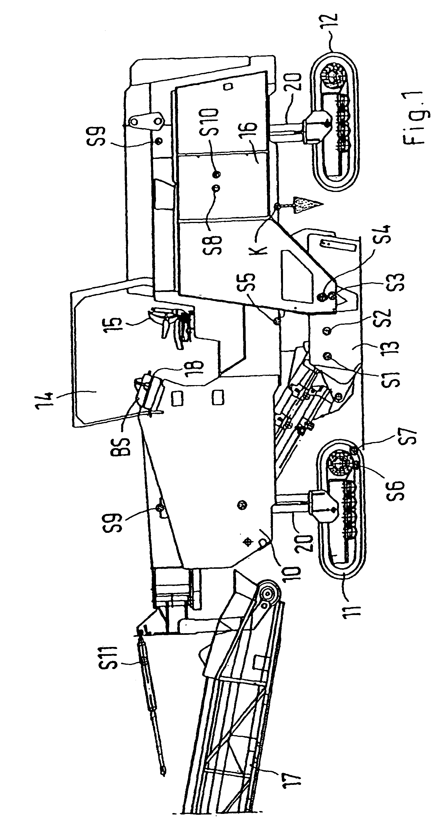
[0040]The lateral view of a road milling machine shows the basic structure and the components of the machine. A machine frame 10 is the basis for the machine, and is supported by two front running gears 11 and two rear running gears 12. In this case, the running gears 10 and 11 can be driven by electric motors or hydraulic motors. These drive mechanisms operate synchronously. It is thus sufficient to assign sensors S6 and S7 for detecting the electrical current or the pressure and the speed to only one running gear, for example 11.

[0041]A milling box 13 is attached to the machine frame 10 between the front and rear running gears 11 and 12. The milling box 13 contains at least one milling roller with chisel holders and chisels. The milling roller is driven by a drive unit 16, which has a Diesel engine, wherein a sensor S8 detects the transferred torque, and a sensor S10 detects other operating data, such as motor rpm, exhaust gas temperature, boost pressure, and the like.

[0042]A came...


PUM

PropertyMeasurementUnit
pressureaaaaaaaaaa
hydraulic pressureaaaaaaaaaa
pressure fluctuationsaaaaaaaaaa

Abstract

A road milling machine having a milling roller with a plurality of chisels. A signal receiving unit is assigned to a machine component which is directly or indirectly involved in the milling process or to another machine component. The signal receiving unit detects an operating condition of the machine component and is connected to a signal emitting unit. An optical detecting device may be assigned to the road milling machine, whereby operations are made easier and the milling pattern is optimized.

Description

BACKGROUND OF THE INVENTION[0001]1. Field of the Invention[0002]This invention relates to a construction machine, in particular for working ground surfaces or for stripping traveled surfaces by a milling roller which has a multitude of chisels.[0003]2. Discussion of Related Art[0004]Construction machines are known, for example, as road milling machines. They have a milling roller equipped with a multitude of chisels, in particular round-shaft chisels. The milling roller rotates during operation and the chisels engage with the ground covering to be worked. The chisels are subjected to continuous wear and must be replaced after a defined time of operation. However, the service life of the chisels largely depends on the milling conditions. Often, the machine operator exchanges the chisels either too early or too late. If they are replaced too early, unnecessary tool expenses arise. If replaced too late, damage to the milling roller can occur.[0005]A further problem in the milling proce...

Claims


Application Information

Patent Timeline
Patent Type & Authority Patents(United States)
IPC IPC(8): E01C23/16B28D7/00E01C23/088
CPCE01C23/088B28D7/00
Inventor HOLL, BERNDHEEMANN, KAYHAHN, GUNTERMAHLBERG, AXEL
Owner WIRTGEN GMBH
Why Eureka
Try Eureka