Digital signal transmission cable and digital video display system

a digital signal and transmission cable technology, applied in the direction of cable termination, coupling device connection, coupling protective earth/shielding arrangement, etc., can solve the problem of not being able to provide intermediate connection components, and achieve good transmission of digital signals over long distances

Inactive Publication Date: 2008-09-09
SUMITOMO ELECTRIC IND LTD
View PDF10 Cites 24 Cited by
  • Summary
  • Abstract
  • Description
  • Claims
  • Application Information

AI Technical Summary

Benefits of technology

[0007]The object of the present invention is to provide a digital signal transmission cable and a digital video display system capable of accomplishing good transmissions of digital signals over long distances even when an image output device not provided with an internally installed compensation circuit for shaping and amplifying digital signals is used.

Problems solved by technology

Until recently, a problem of signal degradation resulting from the distance of transmission and the existence of intermediate connection components was not particularly large because the devices were seldom placed far apart from each other.
Consequently, issue of preventing signal degradation has become extremely important.

Method used


Image

  • Digital signal transmission cable and digital video display system
  • Digital signal transmission cable and digital video display system
  • Digital signal transmission cable and digital video display system

Examples


first embodiment

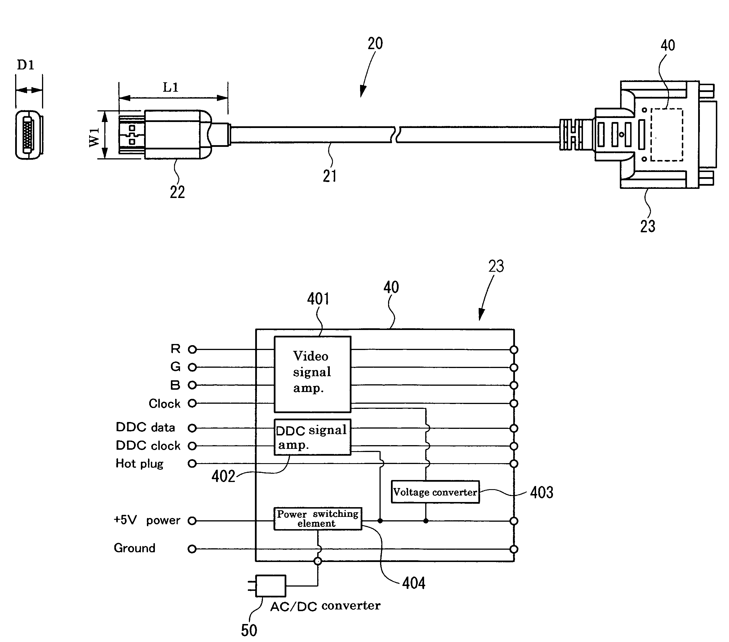
[0022]FIG. 5A is a schematic diagram of a digital signal transmission cable according to the present invention. A digital signal transmission cable 51 has a first metal wire 21 and a first male digital visual interface (DVI) connector 23 compliant with Digital Display Working Group's DVI standard that is mounted to one end of the first metal wire 21 and equipped with a compensation circuit 40 configured to shape and amplify digital signals that propagated through the first metal wire 21.

second embodiment

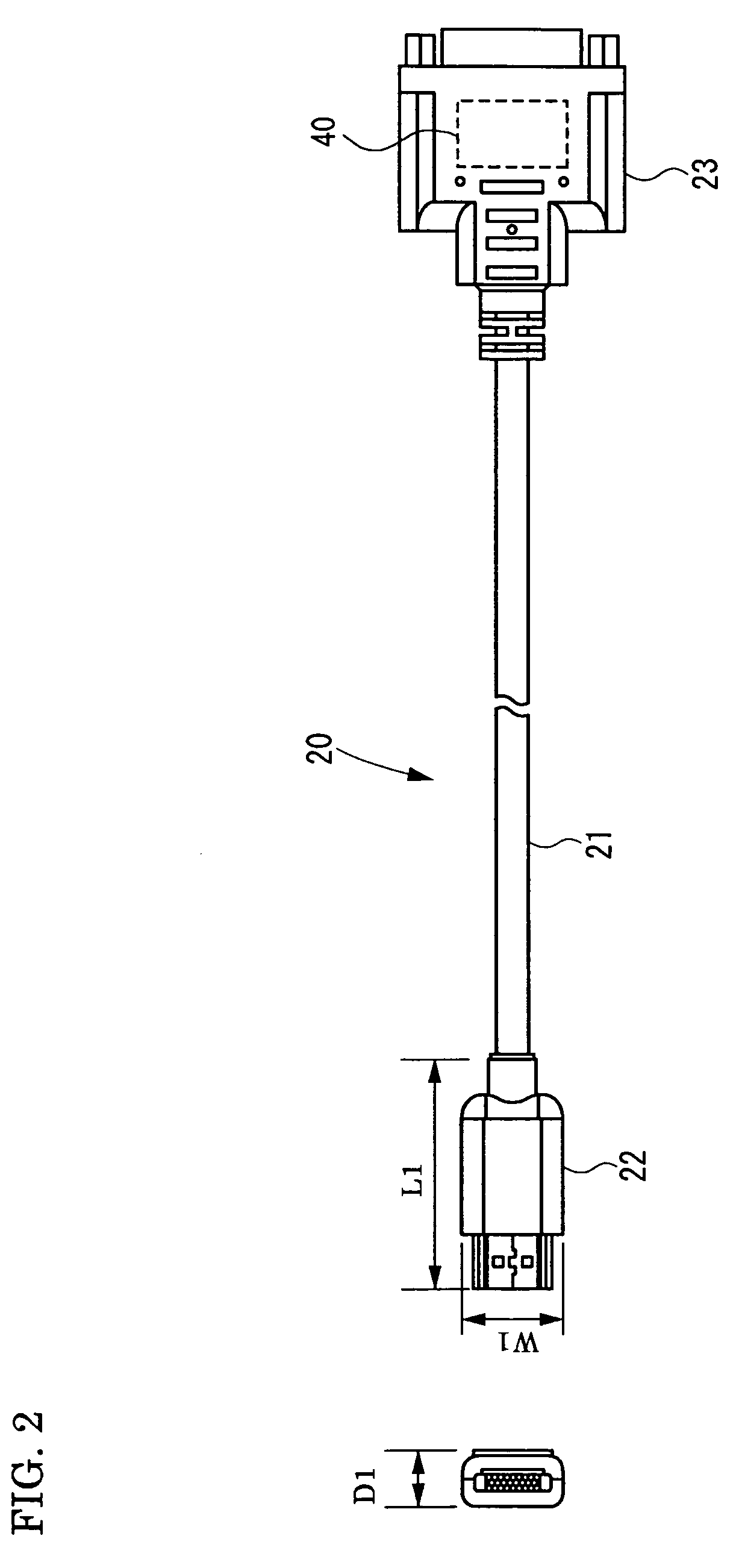
[0023]FIG. 2 is a schematic diagram of a digital signal transmission cable according to the present invention. A digital signal transmission cable 20 is the same as the digital signal transmission cable 51 except that the digital signal transmission cable 20 has a first male high definition multimedia interface (HDMI) connector 22 compliant with HDMI standard is mounted to the other end of the first metal wire 21.

[0024]The digital signal transmission cables 51 and 20 are configured such that a digital signal that has become distorted and / or attenuated while propagating from the other end of the metal wire (i.e., from the first male HDMI connector 22 in the case of the digital signal transmission cable 20) can be corrected with a compensation circuit 40 such that the original waveform and level of the signal are restored. Consequently, digital signals can be transmitted over long distances in a satisfactory fashion even when using a projector, liquid crystal display, or other image o...

third embodiment

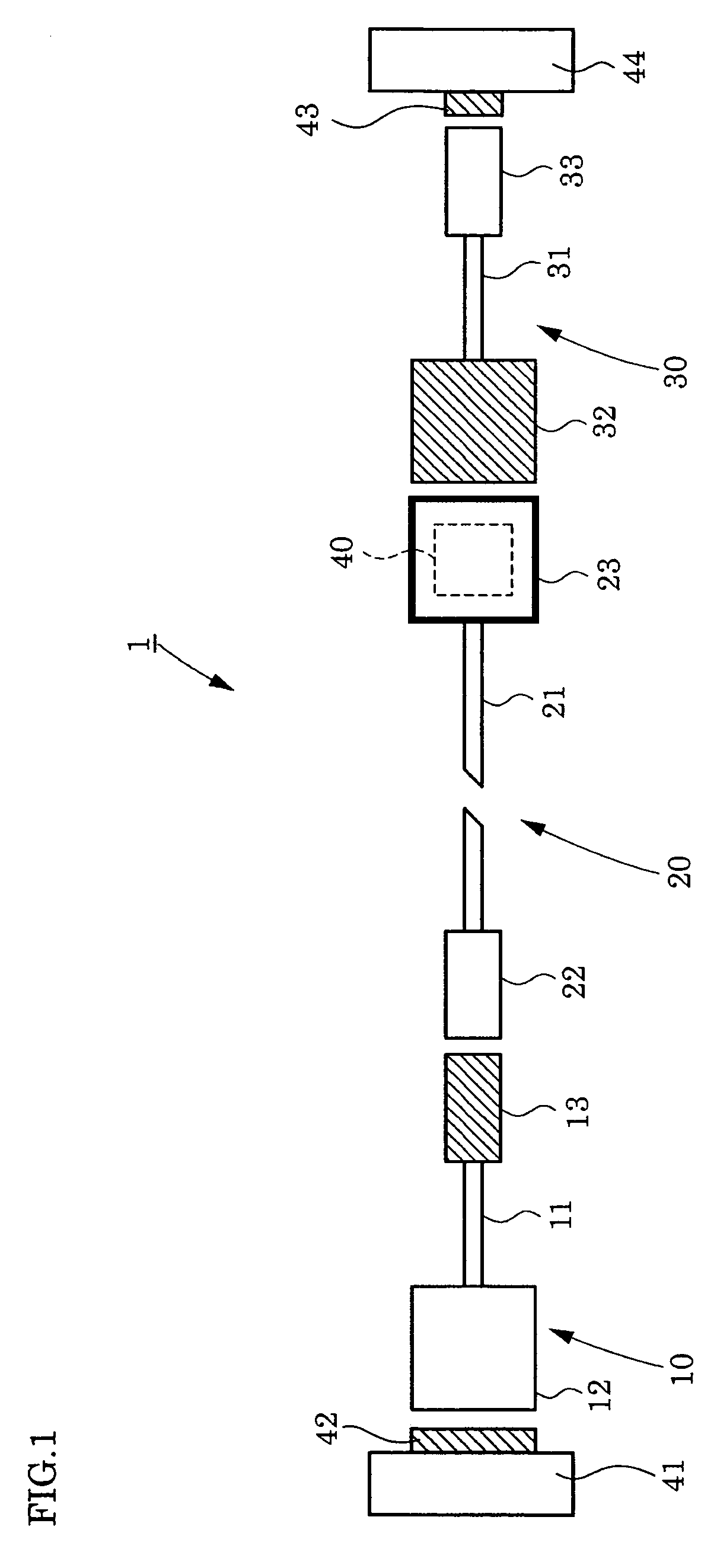
[0025]FIG. 5B is a schematic diagram of a digital signal transmission cable according to the present invention. A digital signal transmission cable 52 is the same as the digital signal transmission cable 20 except that the digital signal transmission cable 52 also has a first DVI / HDMI conversion cable 10 that is connected to the first male HDMI connector 22. The first DVI / HDMI conversion cable 10 comprises a second metal wire 11, a male DVI connector 12 mounted to one end of the second metal wire 11, and a female HDMI connector 13 that is compliant with the HDMI standard and mounted to the other end of the second metal wire 11. The female HDMI connector 13 is connected to the first male HDMI connector 22 of the digital signal transmission cable 20.


PUM


Abstract

A digital signal transmission cable and digital video display system are configured to transmit digital signals over long distances. The digital signal transmission cable has a first metal wire and a male digital visual interface connector that is mounted to one end of the first metal wire and equipped with a compensation circuit. The compensation circuit is configured to shape and amplify digital signals that propagated through the first metal wire. The digital video display system has a digital signal transmission cable and an image input device and an image output device that are connected by the digital signal transmission cable.

Description

BACKGROUND OF THE INVENTION[0001]1. Field of the Invention[0002]The present invention relates to a digital signal transmission cable and a digital video display system that uses the digital signal transmission cable.[0003]2. Description of the Background Arts[0004]With the marked popularity of personal computers and liquid crystal displays, the number of image transmission technologies employing digital signals instead of conventional analog signals has increased. One of the newer digital signal technologies is the digital visual interface (DVI). Currently, the scope of use of DVI technology and products and devices that utilize DVI technology are being developed. Digital signal transmission cables employing DVI technology include metal wire cables that have a transmission range of several meters or optical fiber cables that eliminate the transmission range limitations of metal wires and can transmit over large distances (e.g., see Japanese Published Unexamined Patent Application No...

Claims


Application Information

Patent Timeline
Patent Type & Authority Patents(United States)
IPC IPC(8): H02G15/02
CPCH01R13/665
Inventor KONDA, HIDEYA
Owner SUMITOMO ELECTRIC IND LTD
Why Eureka
Try Eureka