Active compensation of streaks using spatial filtering and feedback control

a spatial filtering and active compensation technology, applied in image enhancement, color signal processing circuits, instruments, etc., can solve problems such as non-uniformity level errors, errors typically arise in raster scan image output terminals (iots), and non-uniformity level errors, so as to improve measurement and printer noise sensitivity, reduce streaking, and reduce streaking

Active Publication Date: 2008-09-09
XEROX CORP
View PDF8 Cites 12 Cited by
  • Summary
  • Abstract
  • Description
  • Claims
  • Application Information

AI Technical Summary

Benefits of technology

[0006]What is disclosed is an image processing method to reduce streaking on a printed sheet. The method uses a negative feedback system to reduce streaking. The feedback system consists of a scanner that scans a printed sheet corrected with an error signal. The error signal is obtained from the scanned image of a previous print off the same printer and the desired output. There are a number of error signals in different positions across the process direction which adjust TRC values. The present invention makes use of a spatial filter representing the spatial frequency sensitivity of the human eye such that only differences (errors) of importance in need of correction are those which can be seen by the human eye. More specifically, a spatially distributed controller is utilized to improve sensitivity to measurement and printer noise. The printer adjusts the incoming bitmap so that each column in the image gives the same response for the same gray level. The printer sacrifices the uniformity of the responses at low and high frequencies where the eye is not responsive so that it can achieve better control at mid-frequencies where the eye is more responsive. At each iteration and for a fixed desired gray-level, the controller processes differences between desired output gray-levels and the values of the gray-levels obtained on the printed output image. A spatial filter is used to emphasize ranges of spatial frequencies critical for a human observer. Then, from these filtered differences (errors), TRC corrections to be applied to the output image are computed using simple scalar integral controllers. Advantageously, since the present invention compensates for defects introduced by lower quality components in a printer, printers can be less tightly specified.

Problems solved by technology

Even small non-uniformity level errors in raster scan IOTs give rise to visually objectionable banding in halftone outputs (e.g., image macro non-uniformity streak artifacts).
Such errors typically arise in raster scan image output terminals (IOTs) due to variations in ROS spot size across the field (which is constant in time (print to print)), donor-roll once-around, HSD wire hysteresis, laser diode variations, LED bar power variation, ROS scan line non-uniformity, photoreceptor belt sensitivity variations, and / or ROS velocity non-uniformity.
Although techniques have been proposed to eliminate such non-uniformity errors by making physical systems more uniform, it is too expensive to control or limit the error to an acceptable level, below which the error will not be detected by the unaided eye.
Fixes have been attempted in the marking process, but not enough latitude exists to fully solve the problem.
However, none of the solutions discussed above implements a technique based in digital electronics.
They are caused by a non-uniform response of at least one of the xerographic components in a given marking engine.
Photoreceptor scratches, HSD-wire contamination, and ROS spot size variations are examples of subsystem problems that can give rise to streaks.
As a result, manufacturing (UMC) and maintenance costs for products increases to cope with stringent image quality requirements.
This is undesirable.

Method used


Image

  • Active compensation of streaks using spatial filtering and feedback control
  • Active compensation of streaks using spatial filtering and feedback control

Examples


Embodiment Construction

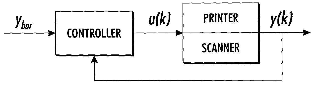
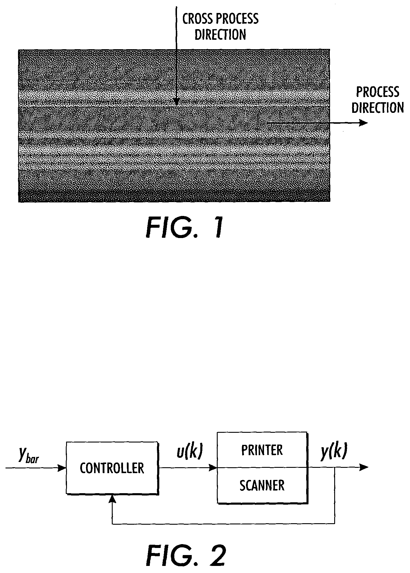
[0010]What is disclosed is an image processing method to reduce streaking on a printed sheet. The method uses a negative feedback system to reduce streaking. The feedback system consists of a scanner that scans a printed sheet corrected with an error signal. The error signal is obtained from the scanned image of a previous print off the same printer and the desired output. There are a number of error signals in different positions across the process direction which adjust TRC values. The present invention makes use of a spatial filter representing the spatial frequency sensitivity of the human eye such that only differences (errors) of importance corrected are those which can be seen by the human eye.

[0011]With reference now being made to FIG. 1, it is important to understand that the process direction is along the line of travel of the print. A cross-process direction is considered to be the direction shown. Also in FIG. 1 are the streaks (lines of varying light and dark pixels on ...


PUM


Abstract

An image processing method to reduce streaking on a printed sheet uses a negative feedback system to reduce streaking. The method scans a printed sheet to produce image data. The method further measures gray-levels of the image data and computes a compensation vector from the measured gray-levels as the difference between a nominal tonal-resproduction-curve and local tonal-reproduction-curves. The compensation vector is applied the image data to be printed. The compensation vector emphasizes ranges of frequencies sensitive of the human eye.

Description

FIELD OF THE INVENTION[0001]The present invention relates to the field of digital imaging and, more particularly, to systems and methods dealing with streaks and other image artifacts that appear on a printed image and which run parallel to the printer's process direction.BACKGROUND OF THE INVENTION[0002]Macro non-uniformity levels have existed in raster scan image output terminals (IOTs) (e.g., xerographic printers) for some time and are a concern for most marking processes. Even small non-uniformity level errors in raster scan IOTs give rise to visually objectionable banding in halftone outputs (e.g., image macro non-uniformity streak artifacts). Such errors typically arise in raster scan image output terminals (IOTs) due to variations in ROS spot size across the field (which is constant in time (print to print)), donor-roll once-around, HSD wire hysteresis, laser diode variations, LED bar power variation, ROS scan line non-uniformity, photoreceptor belt sensitivity variations, an...

Claims


Application Information

Patent Timeline
Patent Type & Authority Patents(United States)
IPC IPC(8): G06K9/40G06K15/00G06T5/00H04N1/407H04N1/409H04N1/46H04N9/64
CPCG06T5/001H04N1/409G06T5/20G06T2207/30176G06T2207/10008G06T5/005
Inventor VIASSOLO, DANIEL E.MIZES, HOWARD A.
Owner XEROX CORP
Why Eureka
Try Eureka