LED-powered dental operatory light

a dental operatory and electric motor technology, applied in the field of apparatus, can solve the problems of inefficient conversion of electricity to visible light, inefficient conversion process, and considerable heat generation of incandescent lights, and achieve the effects of enhancing comfort for patients and clinicians, reducing heat load on patients, and low heat outpu

Inactive Publication Date: 2008-09-16
KAVO DENTAL TECH
View PDF11 Cites 22 Cited by
  • Summary
  • Abstract
  • Description
  • Claims
  • Application Information

AI Technical Summary

Benefits of technology

[0007]The present invention provides an LED-powered light source particularly adapted for use in a dental operatory. However, the light source of the invention is not limited in application to dental operatories. It finds exemplary use in other medical operatories, or in industry or craft applications that benefit from employment of a light source capable of casting substantially shadow-free illumination over an area, or of a visible light source having a reduced power consumption and / or heat output.

Problems solved by technology

However, such incandescent lights suffer from an inefficient conversion of electricity to visible light.
The inefficient conversion process causes production of a considerable amount of heat, and emission of a significant amount of radiation in, or near, the infrared spectrum.
The heat generated by incandescent lighting may sometimes place an undesirable burden on environmental control systems, such as cooling systems used in dwellings.
Both the inefficient conversion process, and removing the undesired heat load from the area near the light, lead to a correspondingly larger than necessary electric utility bill.
Furthermore, in use on an operatory to illuminate an operating site on a patient, the infrared emissions may undesirably dry illuminated tissue, or may produce a feeling of discomfort in the patient.
However, fluorescent bulbs tend to be bulky, and generally produce light of a less desirable color and intensity for many applications.
Furthermore, certain electrical components required in the electric circuit powering the fluorescent bulbs, such as the ballast, tend to produce an undesirable amount of noise.

Method used


Image

  • LED-powered dental operatory light
  • LED-powered dental operatory light
  • LED-powered dental operatory light

Examples


Embodiment Construction

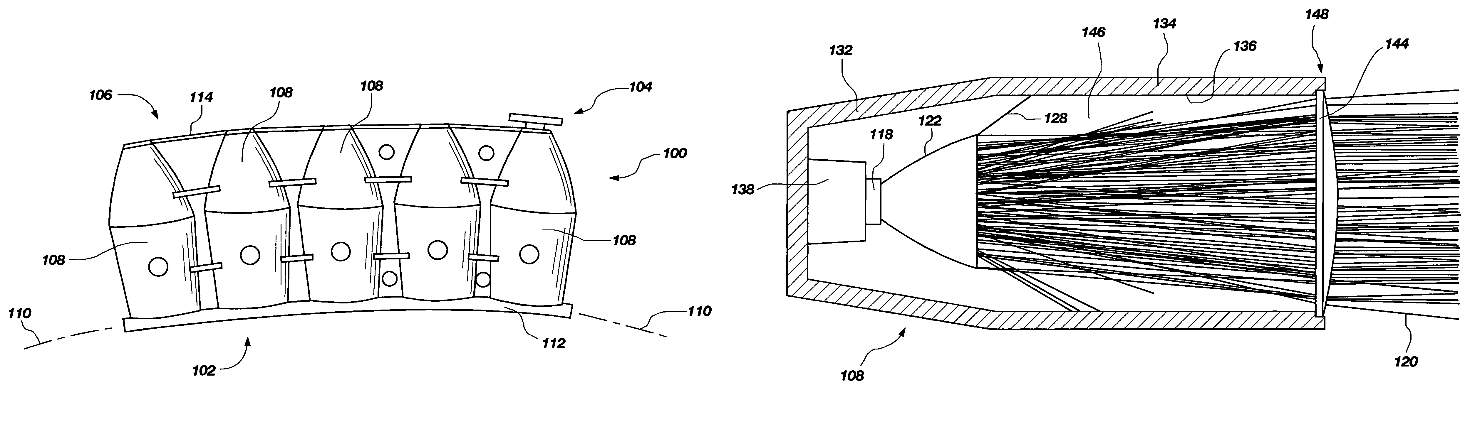
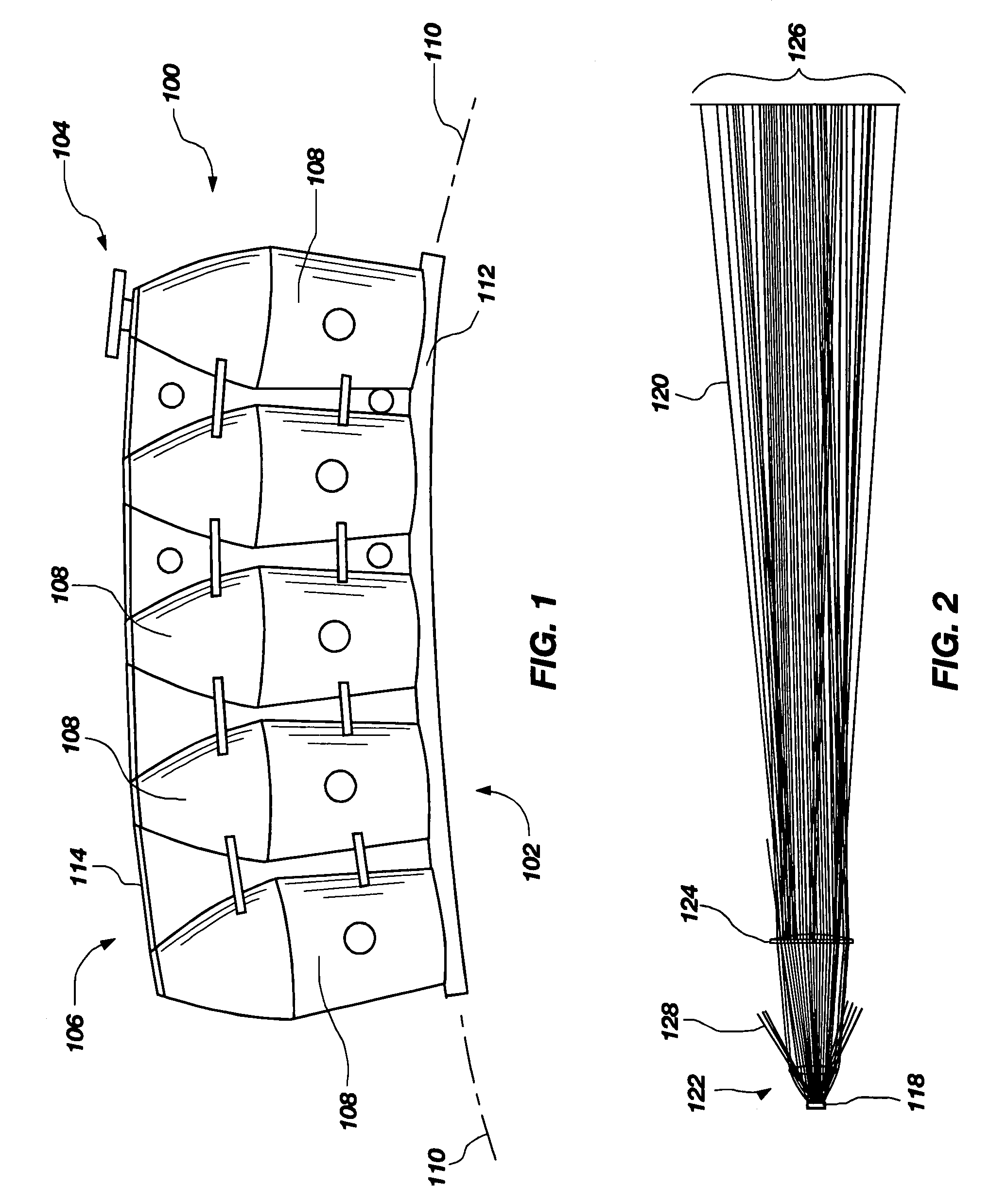
[0031]FIG. 1 illustrates a side view of a currently preferred embodiment, generally indicated at 100, of a light source structure constructed according to principles of the invention. Light source structure 100 may generally be characterized as a lamp. Lamp 100 is powered by electricity, and functions to provide illumination to a work area disposed a distance from the lamp front, generally indicated at 102. Desirably, the work area illuminated by lamp 100 is shadow-free, and appears relatively uniform in illumination color and intensity. For most applications, the illuminated target work area is considered to have an approximately flat footprint and a depth normal to that footprint. That is, the illuminated region is generally structured to encompass a volume disposed proximate the footprint.

[0032]Illustrated lamp 100 includes attachment structure, generally indicated at 104, operable to connect lamp 100 to suspension structure in the work area. Illustrated attach structure 104 is c...


PUM


Abstract

A lamp assembly adapted to cast shadow-free illumination over an area. Typically, a lamp assembly includes a plurality of light modules that are disposed in a spaced apart relationship over an area. Desirably, the lamp assembly is arranged to aim the light output of each module for overlapping summation on a target footprint. Modules generally each include a LED light source, a parabolic reflecting mirror arranged to direct light from the LED, a TIR collimating lens disposed at a distal end of the mirror, and a stray light tube disposed between the LED and a dispersing lens element.

Description

BACKGROUND OF THE INVENTION[0001]1. Field[0002]This invention relates to apparatus that produce visible light. It is particularly directed to an electrically powered light source including a light emitting diode (LED), which is adapted for use in a dental operatory.[0003]2. Background[0004]It has been known for an extended period of time that electricity may be harnessed to create visible light. Incandescent light emitting elements powered by electricity have been used for substantially the same period of time. However, such incandescent lights suffer from an inefficient conversion of electricity to visible light. The inefficient conversion process causes production of a considerable amount of heat, and emission of a significant amount of radiation in, or near, the infrared spectrum. Such infrared emission inherently casts a heat load onto a target along with an illuminating beam. The heat generated by incandescent lighting may sometimes place an undesirable burden on environmental ...

Claims


Application Information

Patent Timeline
Patent Type & Authority Patents(United States)
IPC IPC(8): F21V7/00
CPCF21V13/04F21Y2101/02F21W2131/202F21Y2115/10Y10S362/804
Inventor LOCKAMY, H. THOMASSPENCER, JASON W.MANGLICMOT, DANIEL B.UNSWORTH, AUSTIN E.
Owner KAVO DENTAL TECH
Why Eureka
Try Eureka