
Video signal processing

a video signal and processing technology, applied in the field of video signal processing, can solve the problems of difficult to convert the signal into this form, difficult to derive an orthogonal sampling grid, and difficult to achiev

Active Publication Date: 2008-09-16
GRASS VALLEY LTD
View PDF11 Cites 0 Cited by
  • Summary
  • Abstract
  • Description
  • Claims
  • Application Information

AI Technical Summary

Benefits of technology

The invention provides a method for generating orthogonally sampled digital video from both stable and unstable source material. The method involves sampling the video signal using a constant frequency sampling clock and shifting the samples to an orthogonal sampling grid. The required sample shift is derived from a line phase measure, which is made in integer sample interval units and interpolated to a precision corresponding to a fraction of a sample interval. This method allows for improved video quality and reduced latency.

Problems solved by technology

However, there are applications in which it is difficult to convert the signal into this form; a well-known example is the processing of the output of a domestic video cassette recorder.
In this case the instability of the line frequency makes it difficult to derive an orthogonal sampling grid.
This is difficult to achieve; one problem is that the wide-bandwidth loop is more susceptible to noise than a narrow-band loop would be.
Another problem is that if the loop is capable of operating over a wide frequency range it is less able to phase-lock accurately because of practical limitations to the resolution of the control signal.

Method used


Image

  • Video signal processing
  • Video signal processing
  • Video signal processing

Examples


Embodiment Construction

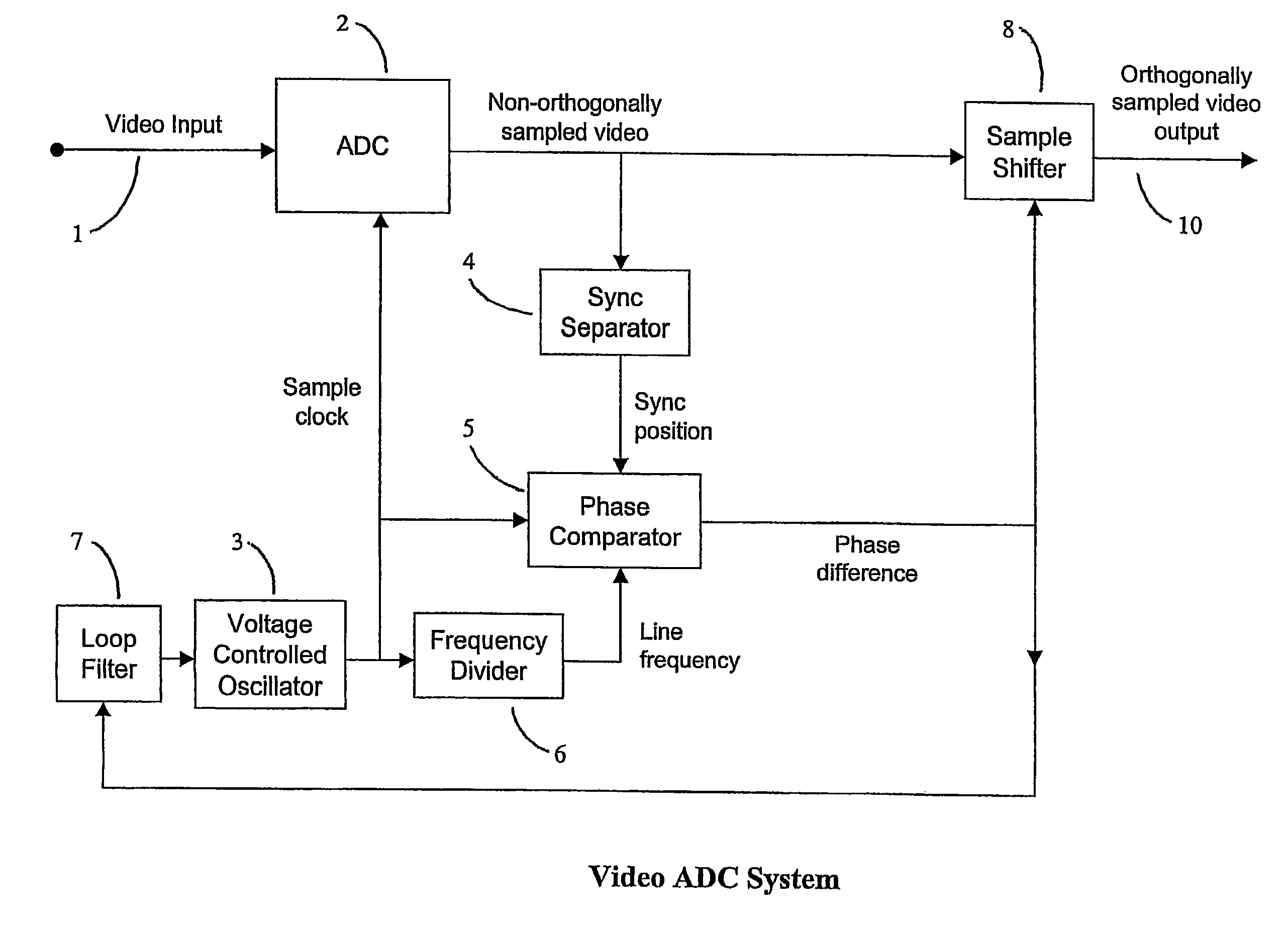
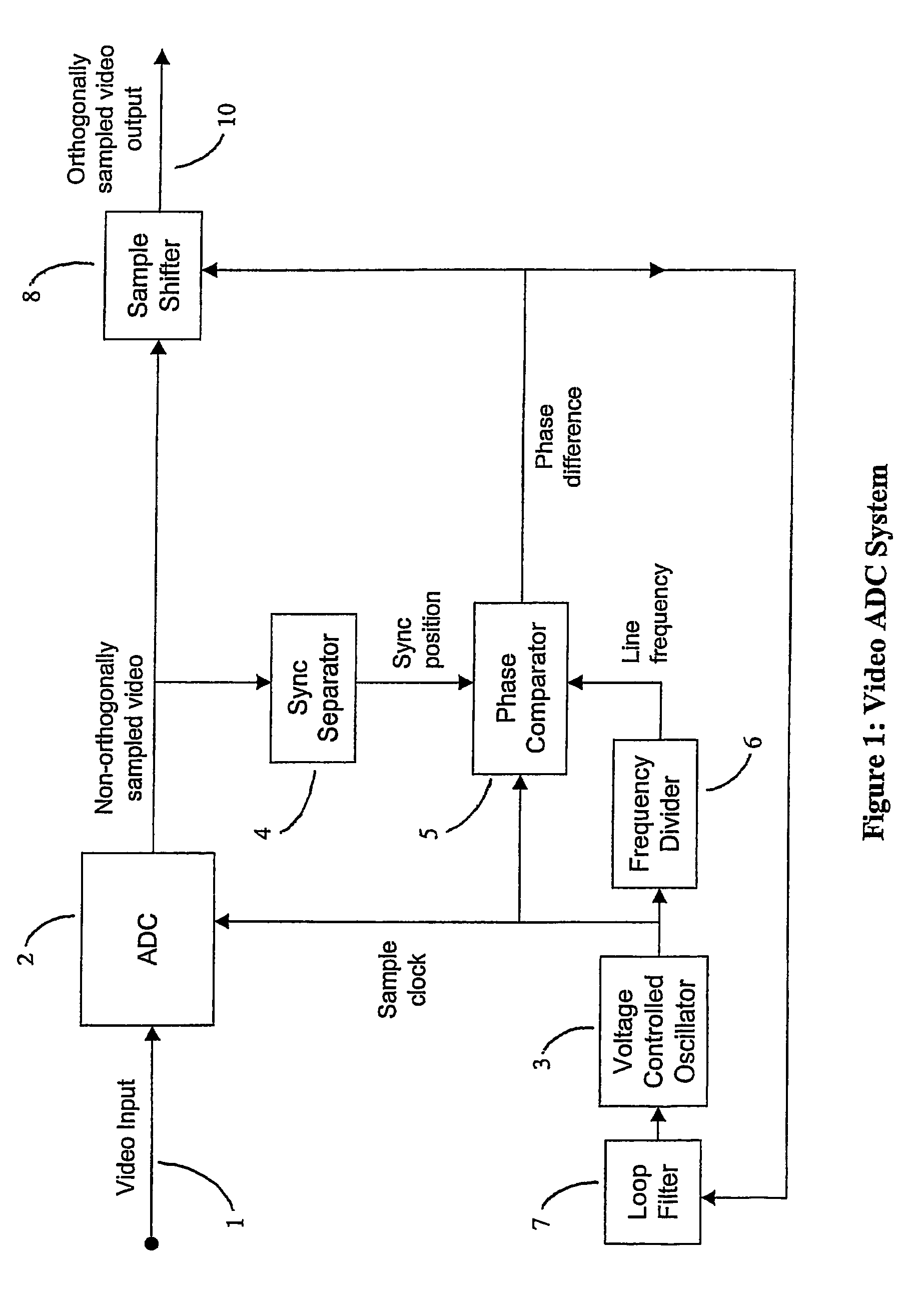
[0017]Referring to FIG. 1, an analogue video input signal (1) is applied to an analogue-to-digital converter (ADC) (2). The sampling clock for this converter is obtained from a stable, voltage-controlled oscillator (3), whose nominal frequency is an integral multiple of the nominal line frequency of the input (1).

[0018]The output samples from the ADC (2) are passed to a digital sync-separator (4) which calculates, to sub-sample accuracy, the position of the horizontal timing reference point (normally the mid-point of the leading edge of the line sync pulse) of each line of the input video signal (1) with respect to the sampling clock from the oscillator (3). A sync phase comparator (5) derives the phase of the detected timing reference point relative to a line frequency signal obtained by dividing (6) the sampling clock frequency by the required number of orthogonal samples per line. The phase difference output of this comparator would typically be expressed as the sum of an integer...


PUM


Abstract

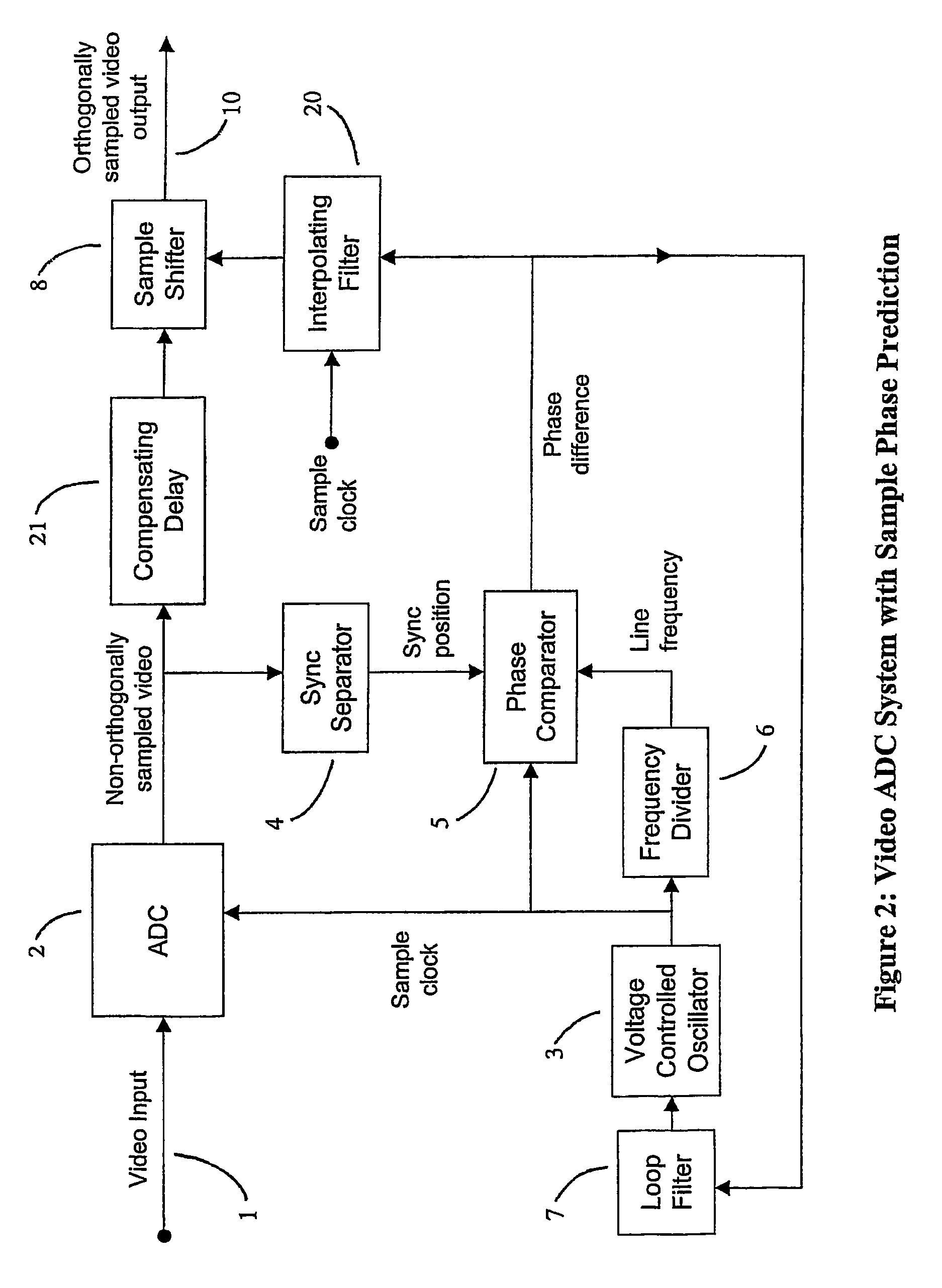
A method of generating an orthogonally sampled video signal based on a line phase measure. In a first aspect the input signal is sampled by a clock locked to the average line frequency of a video input and the resulting samples are time shifted, optionally with or without interpolation, to an orthogonal sampling grid. In a second aspect input samples are taken and shifted to an orthogonal sampling grid according to a line phase measure. The line phase measure can be derived from a number of measurements or interpolated. In one embodiment a delay is employed so that a measure of a later sample is used to shift an earlier sample.

Description

CROSS-REFERENCE TO RELATED APPLICATIONS[0001]This application is a National Phase Application of PCT International Application No. PCT / GB03 / 02348, International Filing Date May 29, 2003, entitled “VIDEO SIGNAL PROCESSING”, which in turn claims priority from Great Britain Patent Application, 0212430.3, filed May 29, 2002, which are both incorporated by reference herein in their entirety.FIELD OF THE INVENTION[0002]This invention concerns the sampling or re-sampling of television signals to achieve an orthogonal sample structure.BACKGROUND OF THE INVENTION[0003]Since the adoption of ITU / CCIR Recommendation 601 the digital processing of television signals has almost always been carried out with an orthogonal sampling structure. However, there are applications in which it is difficult to convert the signal into this form; a well-known example is the processing of the output of a domestic video cassette recorder. In this case the instability of the line frequency makes it difficult to de...

Claims


Application Information

Patent Timeline
Patent Type & Authority Patents(United States)
IPC IPC(8): H04N5/04H04N5/12H04N5/14H04N5/91
CPCH04N5/126H04N5/14H04N5/91
Inventor FLANNAGHAN, BARRYWESTON, MARTIN
Owner GRASS VALLEY LTD
Learn More