
A Method of Measuring Speed ​​Based on Incremental Photoelectric Encoder

A photoelectric encoder, a technology for measuring speed, applied to devices using electric/magnetic methods, etc., can solve problems such as occupying FPGA resources, inaccuracy, and cumbersome decoding process

Active Publication Date: 2019-04-23
威科达(东莞)智能控制有限公司
View PDF11 Cites 0 Cited by
  • Summary
  • Abstract
  • Description
  • Claims
  • Application Information

AI Technical Summary

Problems solved by technology

However, this method needs to use the FPGA to decode the AB pulses of the encoder first, and the decoding process itself is relatively cumbersome and takes up FPGA resources; the number of pulses that are not integers at the beginning and end of the sample calculated after decoding is only The encoder is only accurate when it runs at a constant speed, but it is very inaccurate when it is accelerating and decelerating.
Although improved over the first method, there are still significant limitations

Method used

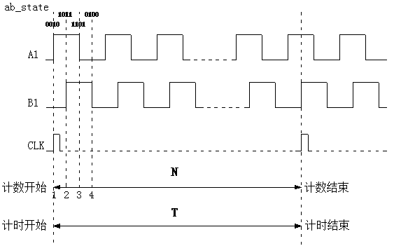

Image

  • A Method of Measuring Speed ​​Based on Incremental Photoelectric Encoder

Examples


Embodiment Construction

[0021] In order to facilitate the understanding of those skilled in the art, the present invention will be further described below in conjunction with the embodiments and accompanying drawings, and the contents mentioned in the implementation modes are not intended to limit the present invention.

[0022] Such as figure 1 As shown in the schematic diagram of the speed measurement method of the present invention, A1 and B1 are AB signals after asynchronous signal synchronization and filtering, and the rising edges of the A1 signal and B1 signal are completely consistent with the rising edge of the FPGA clock signal CLK. It can be seen from the figure that when the encoder rotates forward, when ab_state is equal to 0010, 1011, 1101 or 0100, it is the point where the encoder counter increments by 1, and it is also the point where the timer starts and ends; when the encoder reverses, When ab_state is equal to 0001, 0111, 1110 or 1000, it is the point at which the encoder counter i...


PUM


Abstract

The invention particularly relates to a method for measuring a speed based on an incremental photoelectric encoder. The method comprises: S1, asynchronous signal synchronization is carried out on an A-phase signal and a B-phase signal of an incremental photoelectric encoder; S2, the synchronized A-phase and B-phase signals are filtered to generate a signal A1 and a signal B1 after filtering; S3, a 4-bit state register ab_state is set; S4, the quadrature sampling number of the signal A1 and the signal B1 is set to be N; S5, a counter starts counting; when the counter starts counting and the ab_state is equal to 0010, 1011, 1101 or 0100, one is added to the counter successively; and when the counting value of the counter is equal to the N, the counter latches the counting time T and the counter and a timer are reset; and S6, according to the quadrature sampling number N and the counting time T, a speed of forward rotation of the encoder is calculated. According to the method, the counter and the timer carry out processing at a rising edge of one same clock signal, so that the speed measurement accuracy can be enhanced.

Description

technical field [0001] The invention relates to the field of speed measurement of a motion control system, in particular to a method for accurately measuring speed based on an incremental photoelectric encoder. Background technique [0002] In industrial equipment, the incremental photoelectric encoder is a very widely used speed sensor. When working, it can output two orthogonal pulse signals A and B with a phase difference of 90°. When rotating forward, A leads B by 90°; when rotating reversely, B leads A by 90°; through the pulse calculation of A and B signals , the speed information of the mechanical equipment can be obtained, so that it can be precisely controlled. [0003] At present, there are generally two methods for measuring the speed of incremental photoelectric encoders. The first method is to use the quadrature pulse acquisition module of DSP or ARM to first collect the AB pulses of the encoder, and then calculate the number of pulses collected within a certa...

Claims


Application Information

Patent Timeline
Patent Type & Authority Patents(China)
IPC IPC(8): G01P3/50
CPCG01P3/50
Inventor 王继超冀国文卢东宋兴华吴政宏张凯旋王浩
Owner 威科达(东莞)智能控制有限公司
Learn More