
Directional power detection by quadrature sampling

A technology of power detection and power, applied in the field of signal transmission, can solve the problems of difficult quantity duplication, difficult directional waveguide structure, inflexible frequency-related mechanical and electrical design, etc., and achieve reliable power measurement and control and low cost effects

Inactive Publication Date: 2011-02-23
HARRIS STRATEX NETWORKS OPERATING
View PDF0 Cites 0 Cited by
  • Summary
  • Abstract
  • Description
  • Claims
  • Application Information

AI Technical Summary

Problems solved by technology

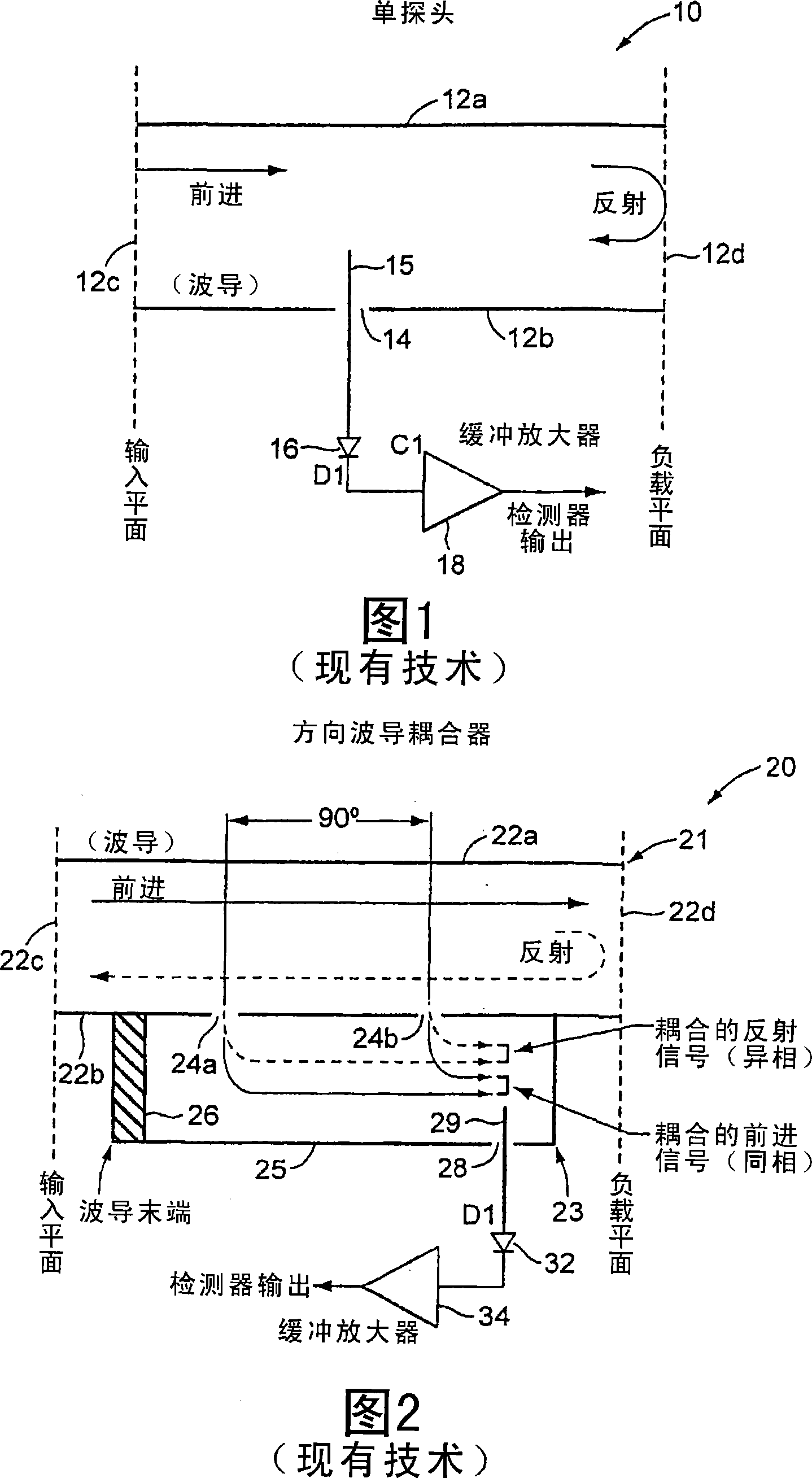
Moreover, the fabrication of waveguides and couplers involves inflexible frequency-dependent mechanical and electrical designs to achieve properties such as isolation and power coupling
Two-part directional waveguide structures are difficult to construct and even more difficult to replicate in commercial quantities

Method used


Image

  • Directional power detection by quadrature sampling
  • Directional power detection by quadrature sampling
  • Directional power detection by quadrature sampling

Examples


Embodiment Construction

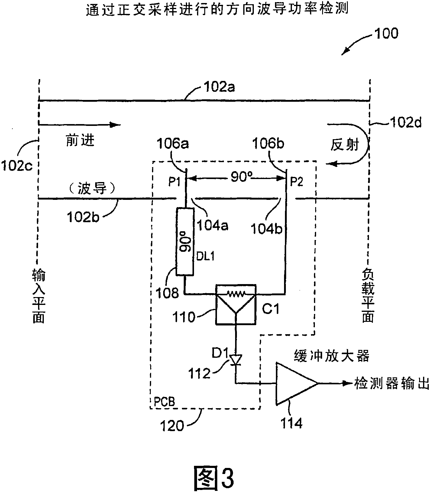
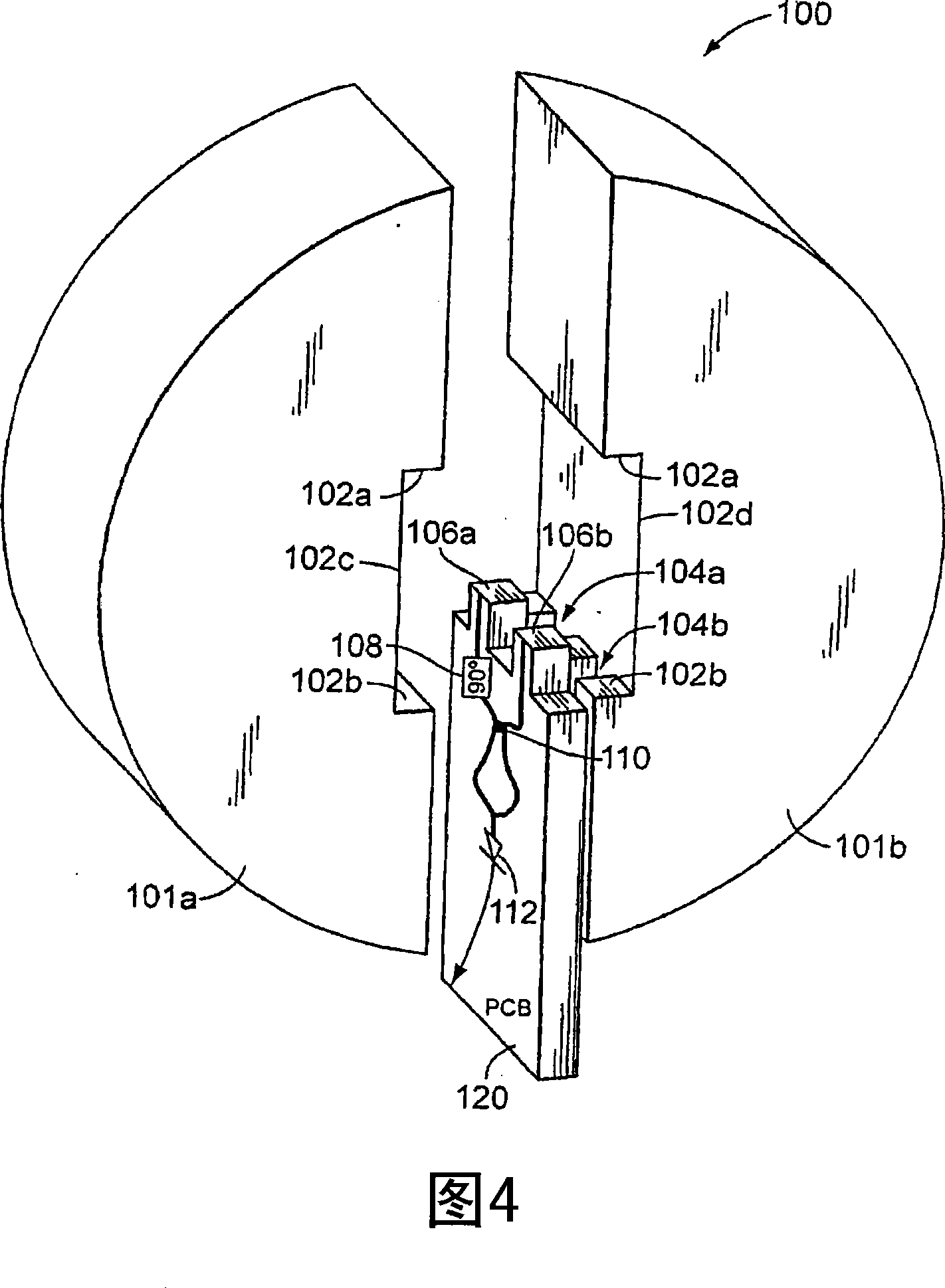
[0029] The present invention is based in part on the observation of the fact that radio frequency signal transmitters are calibrated for specific loading conditions. Typically, the transmitter is calibrated with the test equipment as the load, and then the transmitter is used with the antenna as the load. The load conditions created by the test equipment are not necessarily identical to those created by the antenna, and different antennas have slightly different characteristics which can create different load conditions at the transmitter output. In some cases, a manufacturer may use one type of test equipment to calibrate the transmitter, and then a qualification inspection laboratory may use another type of test equipment to test the transmitter (eg, for FCC rule compliance testing). Transmitter loading conditions may also vary with environmental changes such as temperature and humidity changes. Accordingly, the present invention seeks to provide a means of substantially ov...


PUM


Abstract

Power measurement and control in transmission systems are affected by changes in load conditions. A method and system are provided for detecting and controlling power levels independent of such load conditions.

Description

[0001] introduce technical field [0002] The present invention relates to signal transmission, and more particularly, the present invention relates to the measurement and control of signal transmission power. Background technique [0003] For power measurement and control, the transmitter has a power control feedback loop responsive to a power detector. In a common configuration for high (eg microwave) frequency bands, the power level is measured by a detector in a waveguide connected between the output of the power amplifier and the load. [0004] In general, waveguides are used to transmit high frequency signals, due in part to their low loss characteristics and ability to handle high power. Waveguide elements are constructed in a variety of geometries, examples of which include a "parallel" type with a pair of plates, with a slot in the ground plane on one side of the dielectric substrate with a conductor in the slot, or "coplanar" with no conductors, "dielectric" with...

Claims


Application Information

Patent Timeline
Patent Type & Authority Patents(China)
IPC IPC(8): H01Q11/12G01R31/36H01P1/00G01R23/04
CPCG01R21/12G01R21/01G01R29/0871
Inventor 茵-芳·朝聪·恩古尹罗兰·马蒂安
Owner HARRIS STRATEX NETWORKS OPERATING
Learn More